background image


113903G -System Installation Manual 

13 


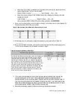
CAUTION 

To prevent electrical shock or damage to your equipment, the Keyed 

Installation Switch (S1), the Main AC Input Circuit Breaker (CB2), and the 

circuit breaker at the input service panel should all be turned off.  The DC 

Battery Fuse(s) should be removed and the Battery Circuit Breaker should be 

turned off. 


9

.  Remove knockouts for AC Input and AC Output in the top left or left side of 

the Inverter Module. AC input conductors and AC output conductors must be 

installed in separate conduits, and emergency and non-emergency output 

circuits must be installed in separate conduits.  


CAUTION 


Do not drill the cabinet; drilling cabinet will void factory warranty; drill filings may 

damage the unit and keep it from operating. If you need larger knockouts, use a 

chassis punch to punch out the appropriate knockout. 


10.  Install the conduit. You must run the AC input service conductors and AC 

output conductors through separate conduits. Emergency output conductors 

and non-emergency output conductors must also be run through separate 

conduits. Emergency output circuits shall be installed in dedicated conduit 

systems and not shared with other electrical circuits as described in NEC 

700-9(b) [CEC Section 47-108]. 


Summary of Contents for Illuminator System CM Series

Page 1: ...System Installation Manual Illuminator System Series CM 5 kW 2 0 kW Installation Guide 44 South Commerce Way Bethlehem PA 18017 1 800 526 5088 610 868 3500 Fax 610 868 8686 Service 610 868 5400 www myerseps com ...

Page 2: ... type batteries contain either acid or alkali and can cause burns to skin and eyes If battery fluid is spilled on skin or in the eyes flush with fresh water and contact a physician immediately 5 Equipment should be mounted in locations where unauthorized personnel will not readily subject it to tampering 6 The use of accessory equipment not recommended by Manufacturer may cause an unsafe condition...

Page 3: ...NTIRE MANUAL AND REVIEW ALL DOCUMENTATION BEFORE ATTEMPTING SYSTEM INSTALLATION FOR SERVICE OR INSTALLATION INFORMATION TELEPHONE 610 868 5400 24 HR HOTLINE FAX 610 954 8227 FOR YOUR PROTECTION PLEASE COMPLETE AND RETURN WARRANTY REGISTRATION CARD IMMEDIATELY ...

Page 4: ...USER SERVICEABLE PARTS inside WARNING Do not install the system outdoors Do not install near gas or electric heaters or in other high temperature locations Use caution when servicing batteries Battery acid can cause burns to skin and eyes If acid is spilled on skin or in the eyes flush with fresh water and contact a physician immediately Equipment should be mounted in locations where it is not rea...

Page 5: ...onnel such as a licensed electrician should perform the system and battery installation and initial startup Risk of electrical shock Please record your unit s model number serial number and part number below You can find these numbers on the label on the inside of the system s circuit breaker door Model Number __________________________ Serial Number __________________________ Part Number ________...

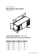
Page 6: ... C H A P T E R 3 BEFORE INSTALLING THE UNIT Installation Dimensions INVERTER MODULE DIMENSIONS 10 X 10 X 26 INVERTER MODULE WITH BATTERY MODULE DIMENSIONS UNIT SIZE WIDTH HEIGHT DEPTH 500 26 20 10 1000 26 30 10 1500 26 40 10 2000 26 50 10 ...

Page 7: ...d the cabinet CAUTION Do not move the unit or the battery cabinet after you install the batteries If you do the unit or battery cabinet and batteries may be damaged CEC Canadian Electric Code requires the unit to be located in a service room If the room is equipped with a sprinkler system the unit must be provided with sprinkler proof covers The system should be connected to the emergency generato...

Page 8: ...ut 45 C 113 F battery life is one fourth of normal Make sure that heaters sunlight air conditioners or outside air vents are not directed toward the batteries These conditions can make the temperature within battery strings vary which can cause differences in the batteries voltages Eventually these conditions affect battery performance Remember that the batteries should be installed as close as po...

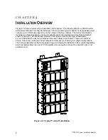
Page 9: ...ttachment for the depicted typical vertical installation shown in figure 4 1 All instructions included in this literature are for this type of installation 4 x 20 bolts that the user must install secure each cabinet to each other There are Electrical Knock Outs in the vertical and horizontal axis to allow inter connectivity in multiple configurations The Vertical installation is the most popular h...

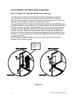
Page 10: ...removed on the Inverter Module and the Battery Module to allow passage of the battery cables After the Electrical Knock Outs are removed the factory provided plastic grommet must be inserted through the hole to provide abrasion resistance for the wires After the plastic grommet is inserted the bolts washers and lock washers should be inserted and tightened down Use the plastic grommet as the align...

Page 11: ...TION Series C M Inverter Module Input AC Line Neutral and Earth Ground Output AC Line Neutral and Earth Ground Battery Positive 4 Places Battery Negative 4 places Fuse Block Input Circuit Breaker CB2 Output Circuit Breaker CB3 Battery Circuit Breaker CB1 Battery Module s Ground Connector ...

Page 12: ... AC voltage inside the unit this is because the unit can supply power from AC line or from its batteries To avoid equipment damage or personal injury always assume that there may be voltage inside the unit Remove rings watches and other jewelry before installing the AC wiring Always wear protective clothing and eye protection and use insulated tools when working near batteries Whenever you are ser...

Page 13: ...ize 90 C Copper Wire This table lists the AWG and mm2 wire size for each circuit breaker size The minimum recommended circuit breaker sizes for each model and voltage application are listed in Table 5 1 The temperature rating of conductor must not be less than 90 C wire Based on the ampacities given in Tables 310 16 of the National Electrical Code ANSI NFPA 70 1993 Table 2 of the CEC and NEC artic...

Page 14: ...e conduits and emergency and non emergency output circuits must be installed in separate conduits CAUTION Do not drill the cabinet drilling cabinet will void factory warranty drill filings may damage the unit and keep it from operating If you need larger knockouts use a chassis punch to punch out the appropriate knockout 10 Install the conduit You must run the AC input service conductors and AC ou...

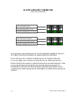
Page 15: ...put use a minimum 12 AWG wire for Line Neutral and Ground Earth Grounding of the system is achieved through the Ground terminal block There is a ground terminal block provided for the input and output connections The terminal block connects to the din rail through a clamping system and the din rail connects to the Chassis through the din rail hardware No additional Ground lugs are required AC LINE...

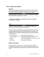
Page 16: ...attery cabinet and shelves are at ground potential as soon as negative connections are made to the batteries It is strongly recommended to make all negative connections to the batteries the last step to prevent any chance of shorting battery positive to ground With the DC fuse removed make connections to battery positive first working your way towards battery negative Leave individual strings of b...

Page 17: ...insulated handles and must be insulated so that they do not short battery terminals Do not allow a tool to short a battery terminal to another battery terminal or to the cabinet at any time Do not lay tools or metal parts on top of the batteries and do not lay them where they could fall onto the batteries or into the cabinet Install the batteries as shown on the battery wiring diagram provided wit...

Page 18: ...s you need the following tools The tools must be insulated so they do not short battery terminals to the cabinet Wear the safety equipment required by local code whenever the doors are open and whenever you are working on batteries Other tools may be necessary for optional batteries Digital volt ohm meter Conductive grease or petroleum jelly 10mm 7 16 open end wrench Brush to apply grease or petro...

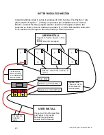
Page 19: ...s Remember that the terminal blocks supplied with the unit and battery cabinets accept up to 10 AWG wire Use the correct type length and gauge of cable make sure your installation meets all applicable electrical codes NOTE As you carry out the following steps use these guidelines If you are using conductive grease apply a thin coating of high temperature conductive grease on each post and every ca...

Page 20: ...approximately 48 VDC The voltage can vary as much as 2 volts depending on the state of charge on the batteries CAUTION If you do not verify that voltage and current direction are correct the equipment may fail Repeat this process for each battery module After all of the battery modules are complete the battery module s can be connected to the inverter module CAUTION Hazardous voltage is present Sy...

Page 21: ...8 x 1 4 20 Bolt and Nut w flat and Lock washers and torque to 40 inch pounds 4 5 Nm maximum USER INSTALL Negative to Positive jumpers in three places Factory provided pre lugged Batteries PRC1235L or NP33 12 4 pieces USER INSTALL Connect two 12 AWG wires Red and Yellow to the Inverter Module from each battery module 48VDC Nominal Positive Wire Red 12 AWG Pre Installed to terminal block Negative Wi...

Page 22: ... internal to the Inverter Module 1 There is a Green 12 AWG ground conductor supplied with each Battery Module as part of the cable kit Cut this wire to the desired length and strip the insulation from both ends 3 8 Then connect one end of the conductor to the ground lug in the Inverter Module There is a dedicated ground terminal block under the battery terminal blocks 2 Connect the other end of th...

Page 23: ... terminal block to 10 inch pounds to secure the wire into the terminal block 4 Repeat this process for additional Battery Modules Negative Wire s Included in the battery cable kit is a yellow wire that will connect the battery module to the inverter module 1 Run the wire between the battery module and the inverter module to get the approximate length required Once the length is established cut and...

Page 24: ...ry cabinets with the same number of batteries These batteries must be the same types as the original batteries The replacement batteries should have the same voltage and ampere hour rating as the original batteries Handle Used Batteries with Care Assume that old batteries are fully charged Use the same precautions you would use when handling a new battery Do not short battery terminals or the batt...

Page 25: ...escription of each test Starting the Unit Before you can set the parameters you must start the system WARNING Verify that the system AC Input Circuit Breaker and Installation Switch are off 1 Turn on the AC input at the building service panel ensure that the systems input breaker CB2 is off 2 Turn on the Battery Circuit Breaker CB1 3 Turn on the System AC input circuit breaker CB2 4 Turn on the In...

Page 26: ...her specific functions of Keys Meter Functions Meter functions are available by pressing the METER keypad to get to the Meter Menu and then pressing the desired function keypad See figure 7 3 Table 7 2 Meter Functions Function Description Keypad Text Voltage Input Measures the AC Input Voltage to the Inverter V IN Voltage Output Measures the AC Output Voltage from the Inverter V OUT Current Output...

Page 27: ...te MM Month 01 Yearly Test Time HH MM Hours Minutes 8 00 Load Reduction AAAA AMPS 0 0A Low VAC Alarm VVVV Volts 1 0V High VAC Alarm VVVV Volts 999 9V Ambient Temp Alarm DDD Degrees Centigrade 70 C Near Low Battery VVVV Volts 43VDC The Day of the Automatic Tests Table 7 5 shows the purpose of each parameter and its factory setting Table 7 5 Factory Setting for Automatic Test Parameter Parameter Det...

Page 28: ...GRAM keypad enter the user password 1234 press the ENTER keypad 2 Press the arrow keypad or keypads are used for scrolling through the menu to the Time parameter HH MM to set the time NOTE Factory default is Eastern Standard Time and with 24 hour formats i e 1 00 PM 1300 hours 3 Enter correct time for your time zone using the NUMBER keypads and then press the PROGRAM keypad to exit Figure 7 3 Fron...

Page 29: ...over to the Inverter and Battery Module s You have finished installing the system Now turn on the output circuit breaker s Fill out and return the manufacturer warranty card to validate the warranty Keep the System Installation Guide and the User s Guide for future reference Notes ...

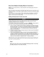
Page 30: ...er above the spring clamp nuts placed in step 2 4 Place the next spring clamp nuts 14 37 on center above the spring clamp nuts placed in step 3 5 Remove cover from Electronics Cabinet and Battery Cabinet 6 Line up the four holes on the back of the Battery Cabinet with the spring clamp nuts from steps 2 and 3 Secure the Battery Cabinet to the spring clamp nuts using 4 20 bolts and 4 flat washers 7 ...

Page 31: ...113903G System Installation Manual 30 Figure 8 1 ...

Page 32: ... nuts 14 37 on center above the spring clamp nuts placed in step 5 7 Remove cover from Electronics Cabinet and Battery Cabinets 8 Line up the four holes on the back of Battery Cabinet 1 with the spring clamp nuts from steps 2 and 3 Secure Battery Cabinet 1 to the spring clamp nuts using 4 20 bolts and 4 flat washers 9 Remove the top left front knockout from Battery Cabinet 1 and Battery Cabinet 2 ...

Page 33: ...113903G System Installation Manual 32 Figure 8 2 ...

Page 34: ...r above the spring clamp nuts placed in step 7 9 Remove cover from Electronics Cabinet and Battery Cabinets 10 Line up the four holes on the back of Battery Cabinet 1 with the spring clamp nuts from steps 2 and 3 Secure Battery Cabinet 1 to the spring clamp nuts using 4 20 bolts and 4 flat washers 11 Remove the top left front knockout from Battery Cabinets 1 2 and 3 12 Remove the bottom left front...

Page 35: ...113903G System Installation Manual 34 Figure 8 3 ...

Page 36: ...ve the spring clamp nuts placed in step 8 10 Place the next spring clamp nuts 14 37 on center above the spring clamp nuts placed in step 9 11 Remove cover from Electronics Cabinet and Battery Cabinets 12 Line up the four holes on the back of Battery Cabinet 1 with the spring clamp nuts from steps 2 and 3 Secure Battery Cabinet 1 to the spring clamp nuts using 4 20 bolts and 4 flat washers 13 Remov...

Page 37: ...o holes on the back of the Electronics Cabinet with the top two spring clamp nuts Secure the Electronics Cabinet to the spring clamp nuts using 2 20 bolts and 2 flat washers Verify that the knockout from each cabinet line up with the other cabinet Return to Chapter 4 Inverter Module and Battery Module Assembly ...

Page 38: ...113903G System Installation Manual 37 Figure 8 4 ...

Page 39: ...113903G System Installation Manual 38 ...

Reviews: