The MyGate Q71S Control Board Installation Manual : Printed 11/02/2013 13:16
6
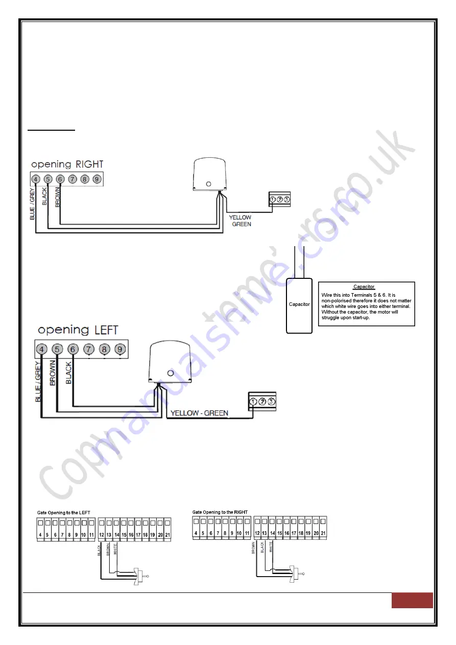
Next stage of the installation is to introduce the motor to the control board. The MyRoller 15 sliding gate
motor is not pre-wired to the control board. You may use 1.5m 4 Core Armoured Cable.
From following your
‘Motor Installation Guide’, the motor is wired into terminals 4, 5 & 6. If you do not have
this guide to hand, below is a re-cap of connections to the control board based on if the gate is opening to
the right and close to the left or opening to the left and closing to the right.
Connecting the motors to the control board
MyRoller 15
Gate Opening to the Right
– Closing to the Left
Gate Opening to the Left
– Closing to the Right
Limit Switch - Connecting to the control board
The limit switch is not pre-wired to the control board. You may use 3 core CAT5 / Alarm Cable to connect.
Wiring diagram below is assuming the gate is opening to the right (default). If you have a gate which opens
to the left, it is required to swap two of the three wires connected from the switch to the control board.
These are Brown and Black. Please swap as illustrated below:


