The MyGate Q71S Control Board Installation Manual : Printed 11/02/2013 13:16
11
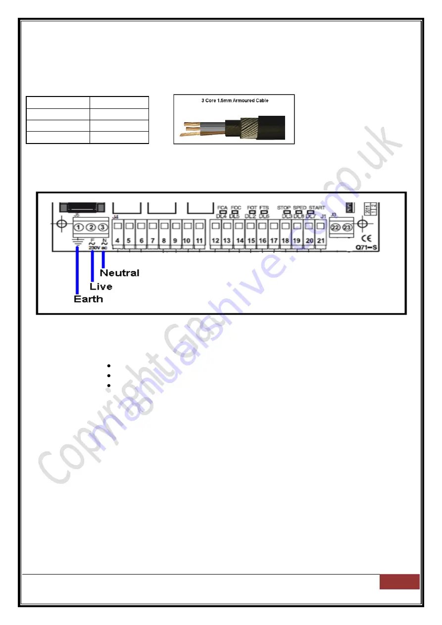
Connecting power to the control board
Connecting power to the control board using 1.5mm - 3 core armoured cable 230v.
Cable identification should be:
Colour
Identification
Brown
Live
Blue
Neutral
Yellow / Green
Earth
Insert the Live (brown) wire to terminal 2 and the Neutral (blue) to terminal 3 and tighten the terminal
screws to ensure good safe contact is made. Please connect your Earth (yellow/green) wire to terminal 1.
Please switch the power supply on. After a few seconds you
will see three LED’s lit:
DL2 (above terminal 15)
DL3 (above terminal 18)
DL6 (above terminal 16)
DL2 Lit =
Photocells status OK, wiring is complete and control board can see the photocells
DL6 Lit =
2nd set of photocells status is OK, wiring is complete and control board can see the photocells.
If second set of additional photocells are fitted (optional).
If a second set is not used, link must be placed between terminals 16 + 17.
DL3 Lit =
Emergency stop button status OK, wiring is complete and control board can see it.
If an emergency stop button is not fitted, a link must be placed between terminals 18 + 21
Now we look to program the remote control key-fob(s) to the control board.


