ASSEMBLY
To make assembly of the home trainer as easy as possible we have pre-assembled the most important
parts. Before you assemble the device you should carefully read these assembly instructions and then
proceed step-by-step as described.
Assembly Instructions
The base has been pre-assembled and diagrams have been included to make the assembly of the
Basic Home Trainer simpler. Good luck.
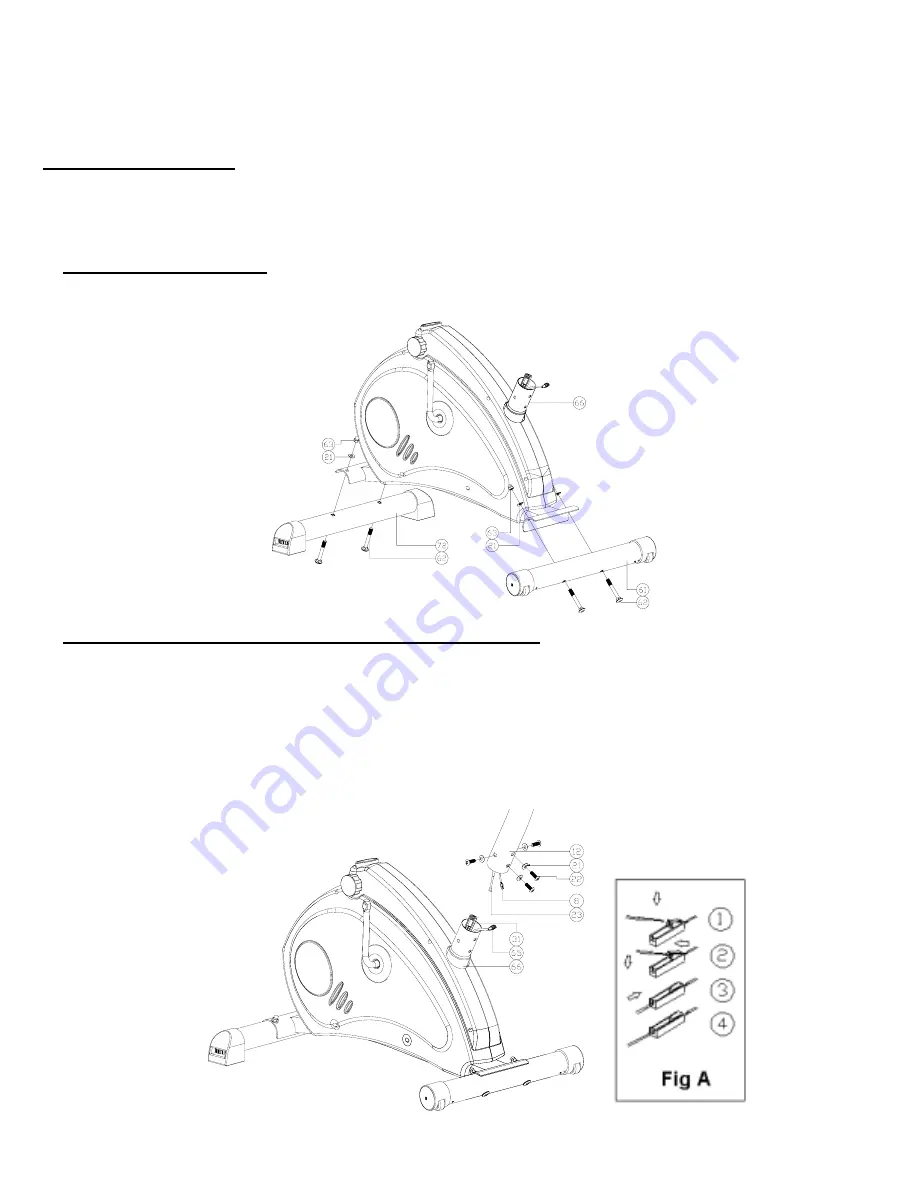
1. Mounting the stand foot
Attach the front and rear stand foot (61/72) to the main frame (66) with four coach bolts (62), four
curved washers (21) and four capsule nuts (63).
2. Mounting the handlebar column and the tension control
Connect the upper computer cable (8) and the lower computer cable (65) ensuring that the connection
is correct so as to allow the signal to be transmitted to the computer then connect the upper resistance
regulator cable (23) and the lower resistance regulator cable (31). (please refer to Fig A). Ensure the
cable connection and inside the frame. Otherwise the cable be damaged.
Then insert the handlebar column (12) into main frame (66). Using the four hexagonal socket screw
(22), four curved washer (21). Turn the resistance regulator (20) back and forth to ensure that it moves
easily. The resistance regulator cable (23,31) must be moved and the procedure repeated if this not
the case.
6
Summary of Contents for BP208
Page 1: ...EXERCISE BIKE MAGNETIC Art Nr BP208...
Page 6: ...Parts Chart 5...
Page 12: ...EXPLOSION CHART 11...


