background image

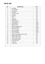
PARTS LIST 


NO 


DESCRIPTION 


Q’TY 


Main Body 

1 PC 

        2   

Front Stabilizer   

1 PC 

        3 

Rear Stabilize   

1 PC 

        4 

Front Post   

1 PC 

        5 

Handlebar w/Grip 

1 PC 

Computer 

1 PC 

Seat Post   

1 PC 

Seat   

1 PC 

Left Pedal   

1 PC 

10   

Right Pedal   

1 PC 

11 

Adjustment Knob   

1 PC 

12 

16 Flat Washer 

4 PCS 

13 

Spring Washer   

3 PCS 

14 

Nylon Lock Nut 

3 PCS 

15 

  M10x80mmCarriage Bolt


4 PCS 

16 
 

25 Curve Washer 

4 PCS 

17 

M10 Domed Nut   

4 PCS 

18 

28 Curve Washer   

4 PCS 

19 

M8 X 20mm Bolt 

6 PCS 

20 

20 Curve Washer 

2 PCS 

21 

Tension Knob w/Upper Tension Cable 

Wire Rear Stabilizer 

1 PC 

22 

Upper Computer Wire 

1 PC 

23 

Middle Computer Wire 

1 PC 

24 

Lower Computer Wire 

1 PC 

25 

Lower Tension Cable   

1 PC 

26 

Hand Pulse Wire 

1 PC 

27 

Crank Arm 

1 PC 

28 

L Type Knob   

1 PC 


Summary of Contents for PL-22100

Page 1: ...MAGNETIC BIKE PL 22100 INSTRUCTION MANUAL...

Page 2: ...g DO NOT wear robes or other clothing that could become caught in the machine Running or aerobic shoes are also required when using the machine 7 Use the machine only for its intended use as described...

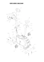
Page 3: ...EXPLODED DIAGRAM...

Page 4: ...Washer 4 PCS 13 Spring Washer 3 PCS 14 Nylon Lock Nut 3 PCS 15 M10x80mmCarriage Bolt 4 PCS 16 25 Curve Washer 4 PCS 17 M10 Domed Nut 4 PCS 18 28 Curve Washer 4 PCS 19 M8 X 20mm Bolt 6 PCS 20 20 Curve...

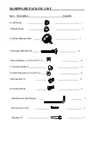
Page 5: ...Left Pedal 1 10 Right Pedal 1 11 Quick Release Knob 1 15 Cariage Bolt M10 80 4 16 Arch Washer 10 5 25 T1 5 4 17 Domed Nut M10 4 18 Arch Washer 8 2 22 T1 2 4 19 Screw M8 15 4 20 Screw M8 20 2 Allen Wra...

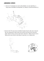
Page 6: ...s 15 Washers 16 and Domed Nuts 17 2 Take the Front Post 4 and join the Middle Computer Wire 23 with Lower Computer Wire 24 Release the Tension Knob 21 from the Front Post 4 and connect the Upper Tensi...

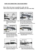
Page 7: ...ting stud end of Post The cable wire fixed in the loop of connector Step c Put the connecting cable wire Step d Fix the salience of the copper end Into the slot of the joint bracket Of the upper cable...

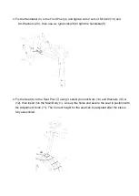
Page 8: ...e knob 28 to tight the handlebar 5 4 Fix the Seat 8 to the Seat Post 7 using 3 sets Nylon lock Nuts 14 and Washers 13 12 then insert into the Main Body 1 Line up the holes and secure the seat in posit...

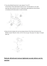
Page 9: ...sit on it Note that the right pedal should be threaded on clockwise and the left pedal on counter clockwise 6 Slide to fix the Computer 6 onto the computer holder of Front Post 4 Note to let the Midd...

Page 10: ......

Reviews: