background image


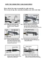
NOTE FOR CONNECTING CABLES AND WIRES 


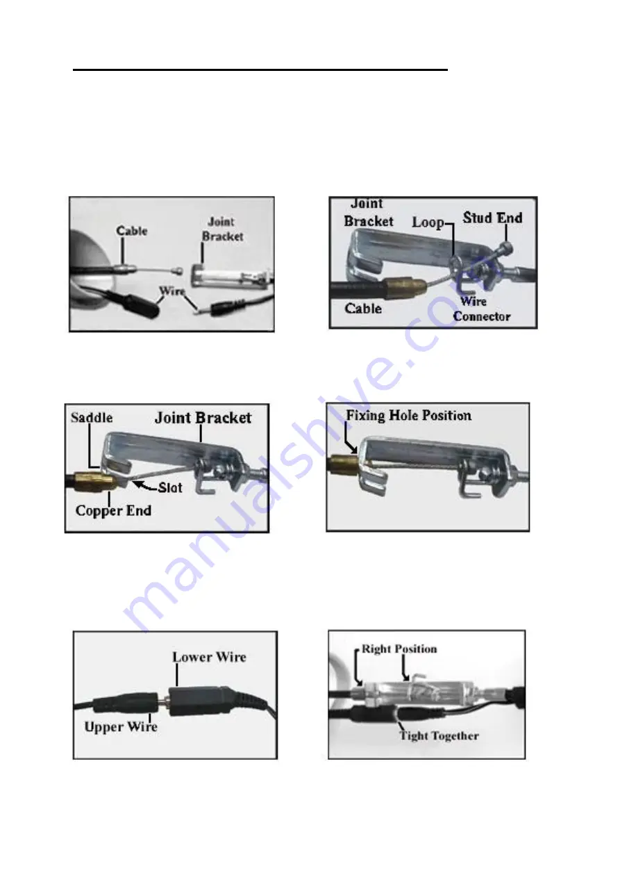
Please follow the steps to assemble the cable and wire. 
This is main doing when assembly handlebar post with main body.   


Step a. Prepare to connect cable and          Step b. Slide the cable wire into the slot of   

Computer wire. Maybe need a                        wire connector of the joint bracket.   
Friend to hold the Handlebar                          Pull up to let the casting stud end of     

                Post.                                                                      The cable wire fixed in the loop of connector.


Step c. Put the connecting cable wire            Step d. Fix the salience of the copper end 

Into the slot of the joint bracket.                      Of the upper cable into the fixing hole   
Pull a little


hard to let the copper                    of the joint bracket.       

End of upper cable jump over the   
Saddle then to the hole. 


Step e. Connect the upper computer wire          Step f. Make sure the cable and wire were 

with the lower computer wire. Push                    right connected. Carefully put back   
together to be whole piece.                                    whole set inside tube before assembly.


Summary of Contents for PL-22100

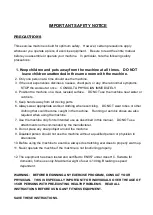
Page 1: ...MAGNETIC BIKE PL 22100 INSTRUCTION MANUAL...

Page 2: ...g DO NOT wear robes or other clothing that could become caught in the machine Running or aerobic shoes are also required when using the machine 7 Use the machine only for its intended use as described...

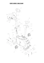
Page 3: ...EXPLODED DIAGRAM...

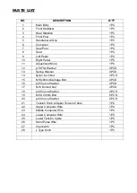
Page 4: ...Washer 4 PCS 13 Spring Washer 3 PCS 14 Nylon Lock Nut 3 PCS 15 M10x80mmCarriage Bolt 4 PCS 16 25 Curve Washer 4 PCS 17 M10 Domed Nut 4 PCS 18 28 Curve Washer 4 PCS 19 M8 X 20mm Bolt 6 PCS 20 20 Curve...

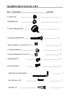
Page 5: ...Left Pedal 1 10 Right Pedal 1 11 Quick Release Knob 1 15 Cariage Bolt M10 80 4 16 Arch Washer 10 5 25 T1 5 4 17 Domed Nut M10 4 18 Arch Washer 8 2 22 T1 2 4 19 Screw M8 15 4 20 Screw M8 20 2 Allen Wra...

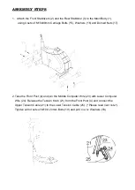
Page 6: ...s 15 Washers 16 and Domed Nuts 17 2 Take the Front Post 4 and join the Middle Computer Wire 23 with Lower Computer Wire 24 Release the Tension Knob 21 from the Front Post 4 and connect the Upper Tensi...

Page 7: ...ting stud end of Post The cable wire fixed in the loop of connector Step c Put the connecting cable wire Step d Fix the salience of the copper end Into the slot of the joint bracket Of the upper cable...

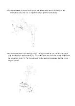
Page 8: ...e knob 28 to tight the handlebar 5 4 Fix the Seat 8 to the Seat Post 7 using 3 sets Nylon lock Nuts 14 and Washers 13 12 then insert into the Main Body 1 Line up the holes and secure the seat in posit...

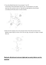
Page 9: ...sit on it Note that the right pedal should be threaded on clockwise and the left pedal on counter clockwise 6 Slide to fix the Computer 6 onto the computer holder of Front Post 4 Note to let the Midd...

Page 10: ......

Reviews: