background image

M Y O S U I T   –   U S E R   M A N U A L  

Page 7 of 53 

Symbols used in this manual 

Symbol 

Meaning of the symbol 


Caution. Please consult the safety instructions. General warning and safety notices. 


General information, tips, and comments about operating the Myosuit. 

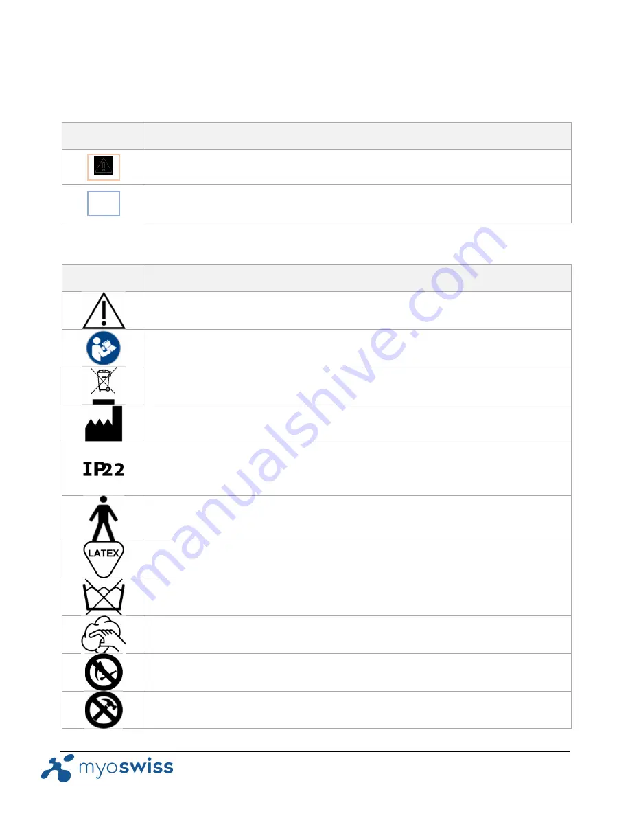
Symbols used in the Myosuit 

Symbol 

Meaning of the symbol 


Caution 


Refer to instruction manual/booklet 


Not for general waste 


Manufacturer 


Protected against solid objects over 12.5mm e.g. hands, large tools. 

Protected against falling drops of water, if the case is disposed up to 15° from vertical. 


Type B applied part 


Contains natural rubber latex 


Do not wash 


Manual cleaning 


Keep away from flames, fire, or excessive temperatures 


Do not drop or impact the battery against hard objects 

Summary of Contents for The Myosuit

Page 1: ...MYOSWISS AG User Manual TheMyosuit...

Page 2: ...TH MYOSUIT REF 1910001 FOR USE WITH MYOSUIT BATTERY REF 1910002 MyoSwiss AG Hardturmstrasse 135 CH 8005 https myo swiss info myoswiss com Document version 3 8 Release date March 24th 2020 This user ma...

Page 3: ...trol functions 14 Remote control button layout 14 Functions of the components of the remote control 15 Configuration screens 16 Training screens 16 2 Actuation unit 17 Components of the actuation unit...

Page 4: ...screen layout and feedback to the operator and user 39 Navigating the training screens 39 Navigating in a training screen 40 Navigating between training screens 41 Changing the assistance and calibrat...

Page 5: ...el approach to provide users with an extra layer of wearable muscles to support their training during activities of daily life Figure I Working principle of the Myosuit The tension of an external tend...

Page 6: ...described in this user manual prior to operating the Myosuit Operator responsibility The operator is responsible to ensure that anyone operating the system has read and understood this user manual an...

Page 7: ...in the Myosuit Symbol Meaning of the symbol Caution Refer to instruction manual booklet Not for general waste Manufacturer Protected against solid objects over 12 5mm e g hands large tools Protected...

Page 8: ...d Keep dry Use only the charger provided for the battery Medical device Reference number Lot number Serial number Applicable classifications EN 60601 1 Protection against electrical shock Internally p...

Page 9: ...the assistance of another person but can be assisted by traditional assistive devices except knee orthoses e g cane crunch ankle foot orthosis Physical prerequisites such as muscle status mobility gr...

Page 10: ...there is visible damage on any components of the Myosuit Please contact MyoSwiss in such cases Stop training immediately if there are faults or abnormalities from the Myosuit Servicing or repairs mus...

Page 11: ...ons of the Myosuit components ID Component Function 1 Remote control The remote control is the main interface to control the functions of the Myosuit 2 Actuation unit The actuation unit is the rigid b...

Page 12: ...includes at least two hip ligaments and two ankle ligaments not shown in the image 6 Tendon routing sleeves Tendon routing sleeves 7 Sensor cables The sensor cables carry the information from sensors...

Page 13: ...tension of the Myosuittendons is kept constant The tension can be adjusted between six levels of tension For example during balance training Concentric force mode In this mode the Myosuit assist the...

Page 14: ...U A L Page 14 of 53 1 Remote control The remote control is the main interface to control the functions of the Myosuit Remote control functions Remote control button layout Figure 2 1 1 Remote control...

Page 15: ...s of the button navigates in a clockwise direction A long press of the button 0 5 seconds navigates in a counterclockwise direction 1 5 Left arrow button In configuration mode the left arrow button is...

Page 16: ...guration screens Detailed information on how to operate the Myosuit is provided in Part 2 of this user manual The following screen samples are shown for general reference Figure 2 1 2 Configuration sc...

Page 17: ...ce that is then transmitted to the user Components of the actuation unit Figure 2 2 1 Actuation unit and its components Functions of the actuation unit components ID Component Function 2 1 Battery The...

Page 18: ...being used This may cause the Myosuit to overheat The cooling vents facilitate the flow of air in the actuation unit 2 4 Tendons The tendons are the elements that transmit the forces from the actuatio...

Page 19: ...Function 3 1 Shoulder straps The shoulder straps help position the Myosuit on the user 3 2 Hip belt The hip belt is the main anchor point to support the forces from the Myosuit on the user The hip be...

Page 20: ...houlder strap attachment The shoulder strap attachment connects the shoulder strap to the inner hip belt via a plastic hook 3 7 Hip ligament attachment The hip ligament attachment connects the hip lig...

Page 21: ...Component Function 4 1 Thigh brace Section of the knee orthosis frame that routes the tendons from the back of the thigh to the front of the thigh 4 2 Shank brace Section of the knee orthosis frame t...

Page 22: ...knee orthosis to the user s shank 4 8 Thigh frame padding The padding on the thigh provides added comfort for the user It should always be used when the Myosuit is in use There are two paddings thick...

Page 23: ...components of the passive elements ID Component Function 5 1 Hip ligament rubber The hip ligament rubber assists the user with flexion of the hip joint It also helps align the knee orthosis with the u...

Page 24: ...with weakness of the ankle dorsiflexor muscles or hip flexors or who may have issues with clearing the ground while walking 5 5 Ankle ligament hook The ankle ligament hook attaches to the laces of the...

Page 25: ...onents of the force routing sleeve Figure 2 6 1 Force routing sleeves Functions of the components of the force routing sleeves ID Component Function 6 1 Outer sleeve The outer sleeve guides the inner...

Page 26: ...be made to determine the size of the hip belt and the padding for the thigh frame 1 Measure and record the circumference of the waist of the user The measurement should be made at the level of the hi...

Page 27: ...ones and extend in the direction of the knee The attachment of the shoulder straps and hip ligaments to the inner hip belt is explained below Figure 3 1 1 Example positions of the shoulder strap and h...

Page 28: ...suit please prepare the system for the user by performing the following steps The sizes are available for review in the user s profile 1 Adjust size of the inner belt Figure 3 1 2 2 Adjust the locatio...

Page 29: ...suit on the user s shoulders using the shoulder straps Figure 3 1 4 2 Attach the hip belt by first closing the inner belt and then tightening the outer belt Figure 3 1 4 Make sure to connect the outer...

Page 30: ...ank strap This strap should sit slightly below the calf muscle d Proximal shank strap This strap sits around the middle of the thigh 7 Optional Tighten the hip ligaments 8 The Myosuit should sit comfo...

Page 31: ...M Y O S U I T U S E R M A N U A L Page 31 of 53 Figure 3 1 4 Steps to don the Myosuit The donning process can be done while the patient is either standing or sitting...

Page 32: ...is sits as shown in Figure 3 1 6 This strap makes a triangle on the back of the user s leg The distance between the straps height of the triangle should be as small as possible and not exceed the heig...

Page 33: ...e the user is either sitting or standing The steps are as follow 1 Turn off the Myosuit by pressing the standby button for 5 seconds A screen to confirm the powering off of the Myosuit will show The o...

Page 34: ...odes of operation while in use Configuration mode and Training mode The typical workflow when using the Myosuit is to 1 Turn on the Myosuit 2 Configure the training session 3 Train with the Myosuit 4...

Page 35: ...ng off the Myosuit Hold down the standby button for two seconds A screen to confirm the powering off of the Myosuit will show The operator can then cancel or confirm the powering off The Myosuit can b...

Page 36: ...guide the training session from a list of available operators a Move down the list of available operators by a short press of the navigation button b Move up the list of available operators by a long...

Page 37: ...een informing the operator that the system is ready for training will automatically appear Figure 4 1 4 right A long press of the action button will move the system into transparency mode The first ti...

Page 38: ...transparent Isometric This mode sets the forces of the Myosuit to a constant value When the assistive forces are engaged the symbol is surrounded by a solid frame Concentric This mode sets the assist...

Page 39: ...on button to move clockwise between 5 fields available 1 current training mode 2 assistance level of the left leg 3 calibration level of the right leg 4 calibration level of the left leg and 5 assista...

Page 40: ...g in a training screen Figure 4 1 6 Navigating within a training screen Using the navigation button short and long presses change between the fields in a clockwise short press and counterclockwise lon...

Page 41: ...sor to the current training mode and use the left and right arrow buttons to navigate between modes Figure 4 1 7 Navigating to a different training mode requires that the operator first navigates to t...

Page 42: ...tor and the user The assistance level may need to be changed as the user is more fatigued or as he or she feels the need for added assistance Calibrating the Myosuit for walking and stair negotiation...

Page 43: ...ng and storing the Myosuit as described below Battery care Proper battery care must be done to ensure safe use of the Myosuit and maximum battery life The batteries supplied with the Myosuit are speci...

Page 44: ...the battery support rails 2 6 and push the battery into the actuator unit You will hear a clicking sound from the battery release button 2 2 indicating the battery is securely in place Charging the b...

Page 45: ...o rupture while in use Inspecting the padding of the knee orthoses frames and straps Check for any signs of cracking on the padding area Check for any signs that the Velcro is coming off the padding I...

Page 46: ...ert can be snoozed by pressing any button The alert message and beeping will show up again within 20 seconds if the issue has not been resolved e g low battery or high temperature of the actuation uni...

Page 47: ...wiss to schedule service Errors If the system detects and error it will immediately stop operation provide auditory feedback with a beep and provide an error code on the remote control screen The erro...

Page 48: ...mmunication error Restart the Myosuit by turning it off and on Please contact Myoswiss if the error re occurs 9 Motor driver right communication error Restart the Myosuit by turning it off and on Plea...

Page 49: ...tient profile and one general configuration file is inserted in the Myosuit Please contact Myoswiss if the error re occurs 22 File not found Check that an SD card with has at least one patient profile...

Page 50: ...rmstrasse 135 CH 8005 Tel 41 43 215 27 15 support myoswiss com MyoSwiss Deutschland GmbH Strasse der Republik 4 Bitterfeld Wolfen 06766 Tel 49 349 4657 9180 support myoswiss com Please include as much...

Page 51: ...mum weight 110 kg User minimum height 150 cm User maximum height 195 cm User maximum abdominal circumference 125 cm Total system weight 5 6kg Performance Walking maximum speed 1 67 m s Knee orthoses r...

Page 52: ...pheric pressure 700 hPa to 1060 hPa Water resistance IP22 per 60601 1 11 per IEC 60529 1989 AMD2 2013 COR1 2019 Storage conditions Parameter Value range Temperature 25 to 70 C Humidity 20 to 90 relati...

Page 53: ...19 Hip belt hook 20 Hip ligament 23 Hip ligament attachment 20 Hip ligament belt attachment 23 Hip ligament length adjustment 24 Inner sleeve 25 Isometric force mode 13 Knee orthosis 12 Left arrow bu...

Reviews: