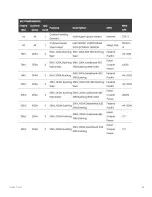
Controls Energization
Energizing the Control Panel will also energize the Meter and Protective Relay, enabling
addition commissioning verifications.
Addition Commissioning Verifications:
1. Proper Battery UPS Energization
2. Networking & SCADA Equipment Energization
3. Metering & Protection Relay Energization
Commissioning Steps:
1. Verify both automotive-style DC fuses are installed on the battery
2. Use a Multimeter (set to DC) to verify the presence of proper voltages at the
following locations on the UPS:
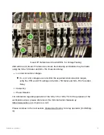
~24V DC (±0.1V, 23.9 - 24.1V) voltage on the top (input) terminals of the UPS
~24V DC (-0.1V/+6.0V , 23.9 - 30.0V) voltage on the top (battery) terminals of
the UPS
~24V DC (±0.1V, 23.9 - 24.1V) voltage on the top (input) terminals of the UPS
3. CLOSE the 10A Fuse Holder [DC Bus 300 / 302b]
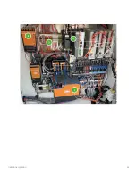
1. Visually verify “Green/Blue/Yellow/Red” power/status indicator lights on the following
equipment:
◦ Hub-E8 - Network Switch (Based on Customer options, there may be additional
devices)
◦ RV50 - Cellular Modem
◦ myPV-IQ - Edge Computer for myPV IQ™ - Remote Interface
◦ BRKR-A - Phase-A Tavrida VFI Control Module
◦ BRKR-B - Phase-B Tavrida VFI Control Module
◦ BRKR-C - Phase-C Tavrida VFI Control Module
2. [Located on the front swing panel dead front] Verify the following components have
signs for energization:
◦ SEL-735 Power Quality Meter (Monochrome LCD Screen should display
information)
◦ SEL-751 Protection Relay (Color LCD Screen should display information)
Initial Energization
54
Summary of Contents for ClearSky
Page 1: ...myPV ClearSky User Manual 1 myPV ClearSky User Manual ...
Page 12: ...Resources 12 ...
Page 14: ...Resources 14 ...
Page 19: ...Resources 19 ...
Page 20: ...Resources 20 ...
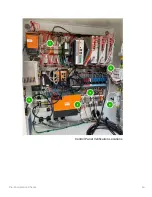
Page 48: ...Pre Energization Checks 48 Control Panel Verification Locations ...
Page 55: ...Initial Energization 55 ...
Page 63: ...Operational Testing 63 The myPV ClearSky may be left in this condition indefinitely ...
Page 68: ...Spare Parts 68 ...
Page 69: ...Spare Parts 69 ...


