5
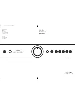
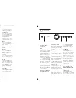
front panel
controls
1
Standby
When the amplifier is plugged into a live wall
socket and the POWER switch is turned ON,
it will power up in “standby” mode and the
LED (Light Emitting Diode) in the STANDBY
button will illuminate. In this mode the
internal circuitry of the MI 120 is powered
up, but disabled so that it consumes very
little power and is isolated by relays at its
inputs and outputs.
When the STANDBY button is pressed the
amplifier circuitry will be activated, the input
used last automatically selected and, after a
few seconds delay, the loudspeaker outputs
will be connected to the amplifier. The LED
in the STANDBY button will change to blue
and the LEDs in the button of the selected
input and the volume control will both light
up. When first switched out of STANDBY
after POWER ON, the CD input will be
selected by default.
When the STANDBY button is pressed again
the amplifier will be returned to standby
mode. The LED in the STANDBY button will
illuminate again and all other LEDs on the
amplifier will be extinguished.
CAUTION: WHEN IN STANDBY MODE THE
INTERNAL CIRCUITRY OF THE MI
120
IS STILL
LIVE, SO ALL SAFETY PRECAUTIONS MUST
BE FOLLOWED.
2
Infra-red receiver window
The infra-red (IR) remote control receiver is
mounted behind this circular window. It must
therefore not be obscured when the amplifier
is to be operated using the remote control
handset. Where possible it is best to arrange
that the IR window is in “line-of-sight” of the
remote handset.
3
Volume control
The volume control adjusts the sound level
for both loudspeakers and headphones. It
does not affect the signals fed to the TAPE 1
and TAPE 2 REC sockets so it can safely be
adjusted whilst making a recording.
The blue LED pointer in the volume control
illuminates when the amplifier is operating.
The pointer may also be used to facilitate
manual operation of the control. When the
MUTE mode is engaged using the remote
control, the volume control pointer will flash
repeatedly to indicate this condition. Always
press MUTE on the remote handset again to
disengage the function before advancing the
volume control setting.
4
Headphones socket
The headphones socket will accept a stan-
dard (6 mm) stereo jack plug or adapter.
All types of headphones of any impedance
may be used, with one exception: electro-
static headphones are usually supplied with
an adapter unit which must be connected
directly to the loudspeaker terminals.
Insertion of a plug into the headphones
socket automatically disconnects the loud-
speakers, silencing them. In order to resume
listening to loudspeakers you must unplug
the headphones from this socket.
The headphones output is not muted when
switching in and out of STANDBY mode,
so it is recommended that headphones
are unplugged from the amplifier before
switching to standby mode and plugged
in again after switch-on.
5
Tape
1
(Monitor)
When you press the TAPE 1 button you can
hear the output signal from a tape deck
connected to the TAPE 1 PLAY sockets on the
rear panel. This is a “toggle” function switch:
you press it once to engage and press again
to disengage. The blue LED in the centre of
the TAPE 1 button illuminates to indicate
that TAPE 1 is engaged. Pressing the TAPE 1
button has no effect on the other input select
buttons. The signal source selected by the
other input select buttons will be fed to the
TAPE 1 REC output sockets, irrespective of
whether the TAPE 1 button is engaged or not.
Thus, if you have a “three-head” tape deck
that permits off-tape monitoring you can
use the TAPE 1 button to switch back and
forth between the source signal and the off-
tape signal, to check its quality, whilst the
recording is in progress.
NOTE: IF THE TAPE
1
BUTTON IS ENGAGED
WITH NO SIGNAL SOURCE CONNECTED TO
THE TAPE
1
PLAY SOCKETS, OR WITH NO
TAPE RUNNING, THEN YOU WILL HEAR ONLY
SILENCE, REGARDLESS OF THE SETTINGS OF
ANY OF THE OTHER CONTROLS.
6
Tape
2
input select
When you press the TAPE 2 button you can
hear the output signal from a tape deck
connected to the TAPE 2 PLAY sockets on the
rear panel. The same signal will also be fed to
the TAPE 1 REC output sockets, so allowing a
standby
phones
tape
1
cd
video
tuner
aux
tape
2
4
operating your
system
TAPE 2 input is selected then tape copies
may be made from TAPE 2 to TAPE 1. It is
NOT possible to copy from TAPE 1 to TAPE 2.
7
Tape
2
input/output
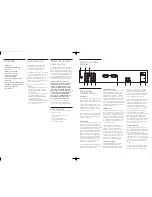
These connectors are suited to any type of
tape recorder, but “off-tape” monitoring is
not possible using TAPE 2. The wiring from
TAPE 2 to your tape deck is identical to the
TAPE 1 wiring described above.
Any source selected for listening, except TAPE
1, will automatically be fed to the TAPE 2
REC output sockets for recording. It is NOT
possible to record from TAPE 1 to TAPE 2.
8
CD input
Connect the audio output cables from a
CD player to these sockets. (Note: this input
is for an audio signal, not for the digital
output from your player.)
If you do not have a CD player then any
other line level source may be connected
to this input.
9
Video input
Connect the audio signal output cables
from a video-related source such as video
cassette recorder or TV set to these sockets.
Alternatively any other line level source
may be connected to this input.
10
Tuner input
Connect the audio output cables from a radio
tuner to these sockets. If you do not have a
tuner then any other line level source may be
connected to this input.
11
AUX input
The audio output from any line level source
may be connected to this input. Alternatively
a Myryad Module may be fitted internally in
your MI 120 to convert this input for other
applications – such as phono cartridge input
for a record player. Your Myryad dealer can
advise you on what Modules are currently
available. Please follow the instructions
supplied with the Module when making
all connections.
12
Ground terminal
This terminal (marked GND) is provided for
grounding a record player connected to the
AUX. input when a Myryad Phono Cartridge
Pre-Amp Module is fitted (see page 3).
English MI 120 ok 29/1/01 10:17 am Page 4


