Step 4. Electrical Connections:
The actuator is fitted with 1100mm of 4-core cable for connection of the system
equipment. The installation will be simplified by the use of an electrical junction box into
which all the system equipment can connect.
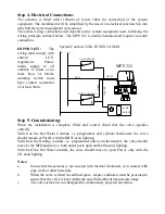
The actual wiring connections will depend on the system equipment used, following the
wiring principle outlined below.
The MPE 322 is double insulated and requires no earth
connection.
IMPORTANT:
The
wiring must comply with
current I.E.E.
regulations. Ensure
mains supply to all
controls is fused at no
more than 3A. Mains
isolating switch must
have contact separation
of at least 3mm.
Step 5. Commissioning:
When the installation is complete, filled and vented, check that the valve operates
correctly.
Switch on the Hot Water Controls, i.e. programmer and cylinder thermostat: the valve
should remain at Port B with the DHW neon lighting.
MPE 322
B
AB
A
System Controls To Be FUSED 3A MAX
C.H. CONTROLS
OFF
ON
BLUE
D.H.W. CONTROLS
WHITE
ORANGE
GR
E
Y
PUMP
BOILER
N
L
ON
OFF
Switch on the Heating controls, i.e. programmer and room thermostat: the valve should
move to the MID position i.e. both outlet ports open and both neons lighting.
Switch off the Hot Water controls, the valve should move to open Port A only with the
CH neon lighting.
Notes:
a.
Ensure that the actuator is not covered with thermal insulation, or in contact with
pipe work or other materials.
b.
When the valve is fitted in confined space, ample ventilation must be provided to
ensure that the valve is kept within the specified ambient temperature range.
c.
The valve actuator is not designed for continuously powered operation.


