background image

Meikon

MAMC-XLINK – Technical Reference Manual

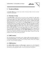
1.2 Block Diagram

The 

MAMC-XLINK

 has the following major features implemented on-board:

1 Lane PCI Express Interface Rev. 1.1 to backplane

1 Lane PCI Express External Cable Interface Rev. 1.0 to front panel

Re-Driver circuitry for boost and reshaping of the PCIe signals

IPMI Controller

Figure 2: MAMC-XLINK Block Diagram

PCIe ReDriver

PI2EQX4402D

PCIe x 1

uT

C

A

 B

ac

kp

la

ne

PCIe x 1

P

C

Ie

 C

a

b

le

MAMC-XLINK

IPMI Controller,

Temp. Sensor,

Control

Power Supplies,

Clock generation,

Hot Swap

Summary of Contents for MAMC-XLINK

Page 1: ...Meikon MAMC XLINK Technical Reference Manual MAMC XLINK Technical Reference Manual V1 1 HW Revision 1 0 1 1...

Page 2: ...by Meikon Ltd 10 Bringsty Common Worcester WR6 5UJ Great Britain Phone 44 1886 822208 Internet http www meikon net and N A T GmbH Kamillenweg 22 53757 Sankt Augustin Germany Phone 49 2241 3989 0 Fax...

Page 3: ...ny direct or indirect damages including lost profits lost savings delays or interruptions in the flow of business activities including but not limited to special incidental consequential or other simi...

Page 4: ...CONTROL SIGNALS 18 4 HARDWARE DESCRIPTION 19 4 1 AMC PORT DEFINITION 19 4 2 DEFINITION OF ATMEGA645 PORT PINS 20 4 3 FRONT PANEL LEDS 22 5 CONNECTORS AND SWITCHES 23 5 1 CONNECTOR OVERVIEW 23 5 2 AMC...

Page 5: ...PIN USAGE PORT G 22 TABLE 11 AMC CONNECTOR CON1 24 TABLE 12 PIN ASSIGNMENT OF THE FRONT PANEL CONNECTOR CON2 26 TABLE 13 ATMEGA645 PROGRAMMING PORT JP1 26 TABLE 14 SWITCH ASSIGNMENT OF DIL SWITCH SW2...

Page 6: ...ent Table 1 List of used Abbreviations Abbreviation Description AMC Advanced Mezzanine Card ATCA Advanced Telecommunications Computing Architecture b Bit binary B byte IPMI Intelligent Platform Manage...

Page 7: ...through a programmable Re Driver circuitry to a PCI Express External Cable Interface Connector on the front panel The MAMC XLINK is member of a family of XLINK boards which enable the connection of d...

Page 8: ...Back View The MAMC XLINK provides master functionality for the cable interface i e provides clock and management signals When connecting it to another XLINK board please make sure that the other boar...

Page 9: ...Rev 1 1 to backplane 1 Lane PCI Express External Cable Interface Rev 1 0 to front panel Re Driver circuitry for boost and reshaping of the PCIe signals IPMI Controller Figure 2 MAMC XLINK Block Diagr...

Page 10: ...l Cable connector The implementation of PCI Express External Cable Interface conforms to the PCI Express External Cabling Specification Rev 1 0 IPMI Controller The MAMC XLINK implements an IPMB interf...

Page 11: ...firmware Power consumption 12V 0 2A max Payload Power 3 3V 0 1A max Management Power Environmental conditions Temperature operating Temperature storage Humidity 0 C to 70 C with forced cooling 40 C to...

Page 12: ...d into Before installing or removing the MAMC XLINK on a carrier board or in a rack Check all installed boards and modules for steps that you have to take before turning on or off the power Take those...

Page 13: ...supply for the MAMC XLINK must meet the following specifications 12V 0 2A Payload Power 3 3V 0 1A Management Power 2 2 3 Automatic Power Up In the following situations the MAMC XLINK will automatical...

Page 14: ...s wherever possible Since January 31st 2005 Meikon N A T has stipulated RoHS compliant components from its suppliers RoHs compliance is also mandatory in the production process 2 3 2 Compliance to WEE...

Page 15: ...ts within the European Community must not be disposed with ordinary waste If you have any questions on the policy of Meikon N A T regarding the Directive 2002 95 EC of the European Commission on the R...

Page 16: ...shows the position of major components Some of the components may not be populated depending on the board version Figure 3 Location Diagram of the MAMC XLINK LEDs MAMC XLINK Location Diagram Re Drive...

Page 17: ...in a satisfactory performance With the MAMC XLINK this can be done either in Software by means of programming the IPMI controller appropriately or by switch settings Please refer to chapters 5 6 5 7...

Page 18: ...an internal differential 100 MHz reference clock The MAMC XLINK is always clock master of the PCI Express External Cable Interface i e the clock is transmitted to the cable interface but not received...

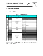
Page 19: ...Options Region unassigned 1 unassigned 2 unassigned 3 unassigned 4 Fat Pipes PCI Express Lane 0 5 unassigned 6 unassigned 7 unassigned Extended Connector 8 Region unassigned 9 unassigned 10 unassigned...

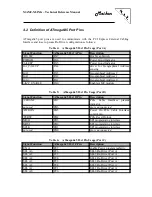
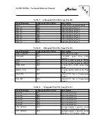
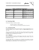
Page 20: ...0 Enable AMC module Table 5 ATmega645 Port Pin Usage Port B Signal Function ATmega645 Port B Pin Description CPRSNT PB7 PCIe Cable Interface present indicator not used PB6 pin is unconnected PWRON PB5...

Page 21: ...nal from Cable Interface SDA PE5 I2 C bus to AMC backplane IPMB SCL PE4 I2 C bus to AMC backplane IPMB RED_LED PE3 controls the red LED on the front panel BLUE_LED PE2 controls the blue LED on the fro...

Page 22: ...es 4 LEDs located on the lower right side of the front panel two of which are mandatory and two of which are optional The MAMC XLINK supports all of these LEDs There are two general status LEDs a blue...

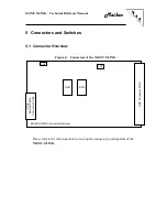
Page 23: ...witches 5 1 Connector Overview Figure 4 Connectors of the MAMC XLINK MAMC XLINK Connector Overview SW1 SW2 PCIe External Cable Connector CON2 JP1 AMC Connector CON1 SW3 Please refer to the following t...

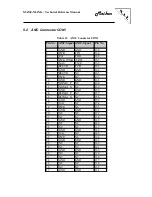
Page 24: ...RESVD NC 163 9 PWR NC 162 10 GND GND 161 11 XLINK1_P NC 160 12 XLINK1_N NC 159 13 GND GND 158 14 RLINK1_P NC 157 15 RLINK1_N NC 156 16 GND GND 155 17 GA1 NC 154 18 PWR NC 153 19 GND GND 152 20 NC NC...

Page 25: ...24 48 PER0_N_P4 NC 123 49 GND GND 122 50 NC NC 121 51 NC NC 120 52 GND GND 119 53 NC NC 118 54 NC NC 117 55 GND GND 116 56 IPMB_SCL NC 115 57 PWR NC 114 58 GND GND 113 59 NC NC 112 60 NC NC 111 61 GND...

Page 26: ...gnal Pin No A1 CPER0_N GND B1 A2 CPER0_P not connected B2 A3 not connected CWAKE B3 A4 SB_RTN CPRSNT B4 A5 CFRECLK_N GND B5 A6 CFRECLK_P not connected B6 A7 not connected CPWRON B7 A8 CPERST CPET0_N B...

Page 27: ...5 on Pos 7 SEL_A6 on Pos 8 not used on 5 7 DIL Switch SW3 The PI2EQX4402D Re Driver device implements four unidirectional ports two of which are used on the MAMC XLINK DIL switch SW3 is used to set th...

Page 28: ...t downstream the PCI Express External Cable Interface by the MAMC XLINK either when programmed by port pin PB4 of the ATmega645 microcontroller or as long as no module is sensed downstream i e CPRSNT...

Page 29: ...als high 6 4 1 Re Driver Strapping Pins Description The Re Driver Strapping Pins set the transmission line driver characteristics Their influence on the transmission line driver characteristics is as...

Page 30: ...E1 Data to a LM75 temperature sensor The address of this sensor is 0 The 2nd I2 C interface is connected to port pins PE4 Clk and PE5 Data This I2 C interface is routed to the IPMB interface of the AM...

Page 31: ...Meikon MAMC XLINK Technical Reference Manual 7 Known Bugs Restrictions Re Driver link sense circuitry not functionable link status not diplayed correctly on LEDs 1 and 2...

Page 32: ...Product Data Rev 2570L 08 07 3 PCI Local Bus Specification Revision 3 0 February 3 2004 4 PCI Express Base Specification Revision 2 0 December 20 2006 5 IPMI Intelligent Platform Management Interface...

Page 33: ...Meikon MAMC XLINK Technical Reference Manual Appendix B Document s History Revision Date Description Author 1 0 01 19 2009 initial revision ga 1 1 05 05 2010 correction of typos ga...

Reviews: