NAT-FMC-SDR4
T
ECHNICAL
R
EFERENCE
M
ANUAL
V1.3
H
ARDWARE
- 14 -
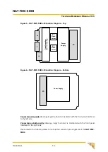
Figure 5
–
NAT-FMC-SDR4-M Location Diagram
–
Top
RF-
Trans-
ceiver
J3
J4
J2
J1
RF-
Trans-
ceiver
Power
Supply
Tr
an
sf
or
m
at
io
n
an
d
D
e-
Co
up
lin
g
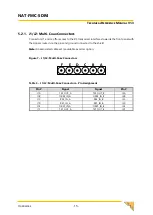
Figure 6
–
NAT-FMC-SDR4-M Location Diagram
–
Bottom
Power Supply
J5
Connectors on top side:
drawings imply the board is orientated with the front panel interfaces
to the left side
Connectors on bottom side:
drawings imply the board is orientated with the front panel
interfaces to the right side
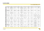
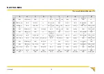
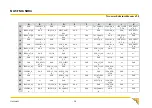
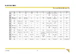
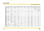
Please refer to the following tables to look up the connector pin assignment of the
NAT-FMC-
SDR4
.


