NATIVE-C1
T
ECHNICAL
R
EFERENCE
M
ANUAL
V1.0
C
HASSIS
D
ESIGN
- 13 -
4.1.
Backplane
4.1.1.
Topology
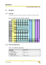
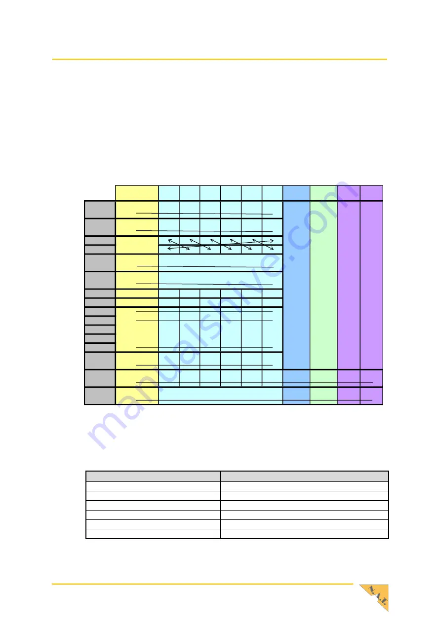
The backplane topology and a sample configuration are illustrated in the following figure.
Figure 3
–
Backplane Topology and Sample Configuration
MCH 1
AMC 1 AMC 2 AMC 3 AMC 4 AMC 5 AMC 6
Power
Module 1
JSM
Cooling
Unit 1
Cooling
Unit 2
Port 0
Fabric A
<
>
>
>
>
>
>
Port 1
Fabric A
<
>
>
>
>
>
>
Port 2
Port 3
Port 4-7
Fabric DEF&G
<
>
>
>
>
>
>
Port 8-11
Fabric DEF&G
<
>
>
>
>
>
>
Port 12-15
Port 17-20
TCLKA
<
>
>
>
>
>
>
TCLKB
<
>
>
>
>
>
>
TCLKC
TCLKD
FCLK
<
>
>
>
>
>
>
IPMB_L
<
>
>
>
>
>
>
IPMB_0
<
><
><
><
>
JTAG
><
><
><
><
><
><
><
><
><
><
><
SATA /SAS
4.1.2.
Electrical Specifications
Table 2
–
Power Distribution Specification
Parameter
Characteristic
Payload Power
Current minimum
10 A
Maximum Voltage Drop
<100 mV @ 7.6 A
Management Power
Maximum Current
3.0 A
Maximum Voltage Drop
<2 0mV @ 150 mA


