NATIVE-C1
T
ECHNICAL
R
EFERENCE
M
ANUAL
V1.0
C
HASSIS
D
ESIGN
- 36 -
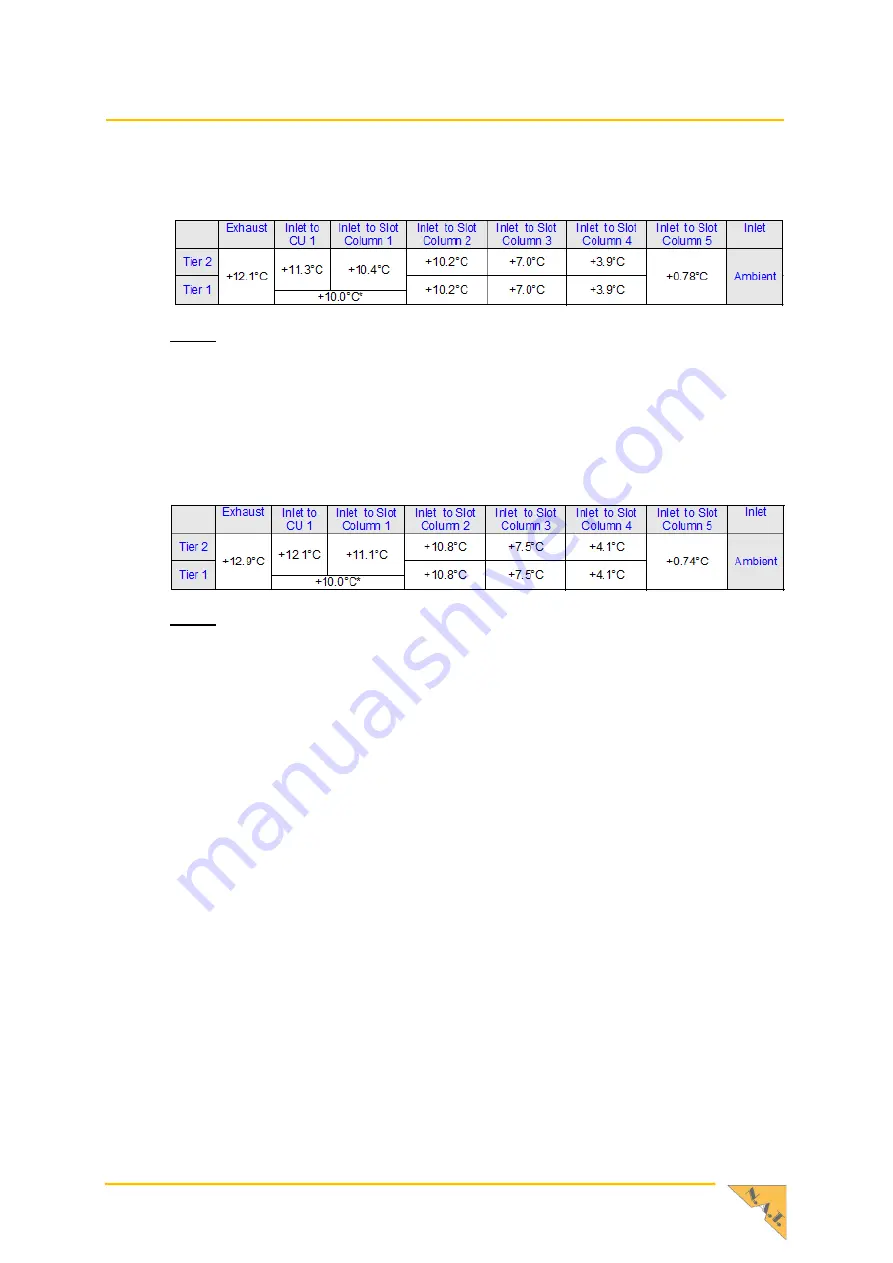
Figure 14
–
Temperature Raise
Note:
Filler Panel Bay: T-Rise=0°C because of no power dissipation.
The figure below illustrates the temperature raise for power distribution shown in the table
above in case of a single air mover failure.
Figure 15
–
Temperature Raise with Air Mover Failure
Note:
Filler Panel Bay: T-Rise=0°C because of no power dissipation.


