background image


BX5 


15 


Fig. 35 

Only for flip-up / jet helmets

:  


Secure the neck roll (

left side

), being careful to slide 

the  neck  roll  plastic  ring  behind  the  microphone, 
then clicking it in the press stud. (Fig. 35)


Secure  the  neck  roll  (right  side)  by  hooking  up  the 
plastic ring to the press-stud.


Warning:

 Always verify the proper length of your chinstrap and adjust it if necessary, referring to the 

specific helmet instructions.


Warning

: After the 

BX5

 is installed on the helmet, make sure the microphone is properly positioned in 

front of your mouth, if necessary adjusting the moveable element.  

Warning: 

The wind protector, supplied as standard equipment with helmets that can be opened, may 

make it more difficult to open and close the chin guard when the microphone is installed. 


4.


REMOVING THE SYSTEM 

To remove the system from the helmet, proceed as for the installation, by removing the various parts. 

Important

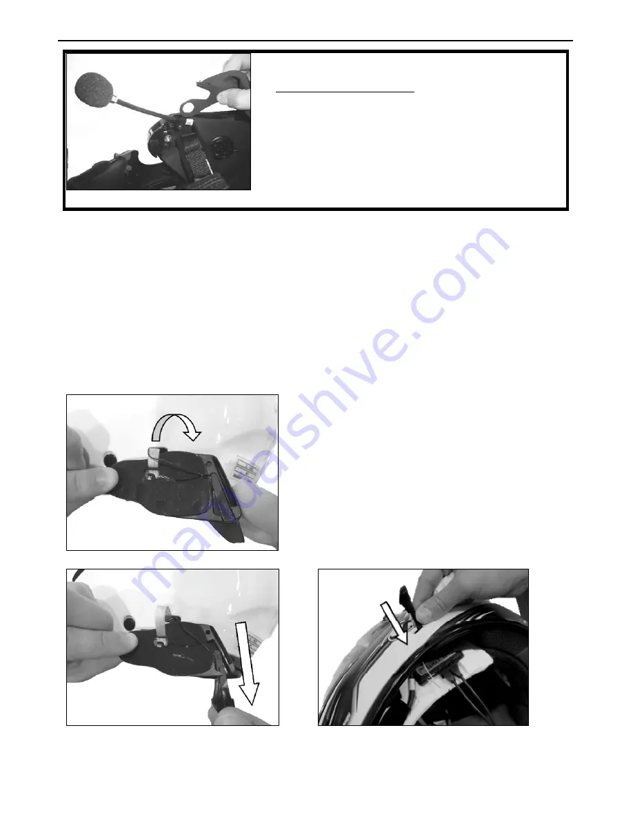
: to remove the keypad support, proceed as follows. 


Fig. 36 


Remove the keypad support from the helmet 
shell (Fig. 36); 


Take  out  the  antenna  from  the  plastic 
support of the keypad (Fig. 37); 


Remove  the  Flex  cable  of  the  keypad  from 
the connector found on the electronic card;  


Now completely  remove the  keypad support 
from the helmet;   


Bring  the antenna inside the helmet,  passing 
it  through  the  hole  in  the  helmet  shell.  (Fig. 
38). 


Fig. 37 


Fig. 38 

The  keypad  support  can  be  removed  in  case  you  decide  to  no  longer  use  the  system.  However,  it 
cannot  be  reused  again  as  it  will  have  lost  its  adhesive  properties.  Contact  your  local  dealer  to 
purchase a new keypad support that will stick properly to the helmet shell. 

Summary of Contents for BX5

Page 1: ...n com it Firmware Version 1 0x REFERENCE STANDARDS The products of the N Com line are in compliance with standards as per the table below BX5 The Bluetooth system complies with the main safety requir...

Page 2: ......

Page 3: ...6 2 Managing two mobile phones or Bluetooth devices 18 7 MUSIC VIA BLUETOOTH A2DP BLUETOOTH PROTOCOLL 18 8 MUSIC VIA CABLE 18 9 SATELLITE NAVIGATOR FOR MOTORCYCLES 19 9 1 Navigators on Smartphone Sma...
Page 4: ...ffic Regulations and then answer the call Do not make any calls while riding Stop your vehicle in a safe place in compliance with Traffic Regulations and then make the call Adjust the volume so that i...

Page 5: ...ion always turn to your local dealer The helmet is a safety device Tampering with it and or with the electronic system inside the helmet in addition to invalidating the product warranty can also lead...

Page 6: ...icates that in the European Union the product is subject to separate collection at the end of its useful life Do not dispose of these products together with undifferentiated urban waste The proper dis...

Page 7: ...package contains e box Adesive Keyboard Microphone Rechargeable battery Battery charger Micro USB jack wire Adhesive strips for cable Microphone foam Microphone securing stickers Adhesive strips for l...

Page 8: ...the helmet Fig 2 then remove the cheek pad by pulling it upward Warning in case the polystyrene cheek pad is damaged during this operation please contact your local dealer to replace it Cut out the r...

Page 9: ...abric securing points Fig 8 Keep the foam used to cover the speakers housing in case you wish to use the helmet without the Bluetooth Kit system Fig 9 helmets X702GT X701 X603 Fig 10 helmet X702 In ca...

Page 10: ...b Make sure that the fluorescent band is facing the inside of the helmet On certain helmets the housing for the microphone rod must be created by cutting out the helmet border gasket along the pre cu...

Page 11: ...Fig 17 Fig 18 Fig 19 Position the right hand side speaker in the specific cheek pad housing and secure it using the specific adhesive Fig 19 Reposition the right polystyrene cheek pad in its housing...

Page 12: ...Fig 22 Secure the wiring underneath the plastic tab Close the cut parts using the cable fixing adhesives Fig 23 Fig 22 Fig 23 3 6 Positioning the e box Fig 24 Connect the microphone to the e box Fig 2...

Page 13: ...ake sure that the adhesive keyboard sticks properly Before you apply the keyboard make sure that the shell area is completely clean and grease or dirt free Only for Jet helmets or flip up helmets Carr...

Page 14: ...takes up to 24 hours for the keyboard to stick completely During this time do not expose the helmet to atmospheric agents Hook up the flex cable of the adhesive keyboard to the e box Fig 34 Repositio...

Page 15: ...o open and close the chin guard when the microphone is installed 4 REMOVING THE SYSTEM To remove the system from the helmet proceed as for the installation by removing the various parts Important to r...

Page 16: ...nected to the PC using the USB cable supplied with the system The functions that can also be managed from the N Com Wizard are listed here below with the specific icon The N Com system is preset to be...

Page 17: ...e and keep them pressed for 2 seconds Manual phone connection Press on and keep it pressed for about 2 seconds Manual phone disconnection Press and keep it pressed for about 4 seconds Conference call...

Page 18: ...function Pause When the player is connected and playing music briefly press on Next track Skip When the player is playing music press for 2 about seconds Previous track Rew When the player is playing...

Page 19: ...en and the Conference setting is stored for future GPS communications N B The GPS Conference function can only be used with the Rider Pillion Passenger intercom channel 1 and not with the Bike to Bike...

Page 20: ...les that can be hooked up the STANDARD configurations allows up to 3 different motorcycles to be hooked up to the BX5 system while the FRIENDS configurations allows up to a total of 6 Important If you...

Page 21: ...ey three times Disconnection of active intercom Briefly press n Con FRIENDS CONFIGURATION active Call CHANNEL 4 Briefly press on Call CHANNEL 5 Press the on key twice Call CHANNEL 6 Press the on key t...

Page 22: ...mit the phone connection confirmation beep 6 To activate communication between two helmets briefly press on the N Com system the key pertaining to the position in which helmet B was stored Intercom B...

Page 23: ...tery is low From the first message the system has a 1 hour autonomy Warning is given every 10 minute 15 2 Charging the system To charge the system hook it up to the battery charger or to a USB outlet...

Page 24: ...2 sec Call transfer 2 sec Manual Device Connection 2 sec Manual Device Disconnection 4 sec Turning on the Conference function X Turning off the Conference function X Intercom Connection CHANNEL 1 X D...

Page 25: ...e system turned off 4 sec Turning on off the RDS X Turning on off the Smart Navi System 2 sec Pairing up secondary mobile phone or device 2 sec Pairing up CHANNEL 1 X Pairing up CHANNEL 2 x2 Pairing u...

Page 26: ...essories that are not part of the N Com product range Moreover the warranty does not cover product defects caused by fortuitous events modifications or adjustments causes of force majeur or damages de...

Page 27: ...n with regenerated components with equivalent functions The replaced parts or components shall become property of Nolangroup THIS WARRANTY VOIDS AND REPLACES ANY OTHER WRITTEN OR VERBAL WARRANTIES PRO...

Page 28: ...EN 18 WARRANTY REGISTRATION FORM Product name BX5 Identification code Buyer s Information Name Last name Address Phone e mail Dealer s stamp Date of purchase...

Reviews: