10
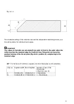
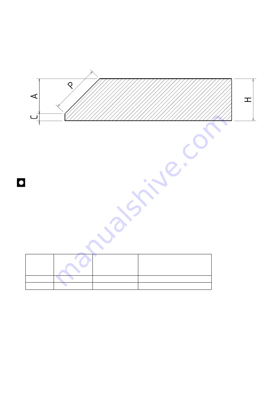
Fig. 11.1.1
For orientation setting of the reduction size and the independent machining process, use
the setting tables for individual bevel angles.
Important:
The values in the table are calculated from point 0. Point is the point when the
miller touches the material edge for the first time. This point can be set by
gradual turning of the thrust plate (fig.10.0.1 position G) and placing to the
material edge.
45° -
For full bevel (P=10mm) is required, turn the thrust plate by 40 revolutions
Chip no.
Hypotenuse
P
Bevel height
A
Number of rpm of the
thrust plate
(Fig.10.0.1 pos. G)
I.
5mm/0,19 in
3.5mm/0,13 in
2 Revolutions
II.
10mm/0,39 in
7.7mm/0,30 in
+ 2 Revolutions


