The oNeTRAK Manual
The oNeTRAK Manual
DCC WIRING TIPS
6
ONETRAK JUNCTION
11
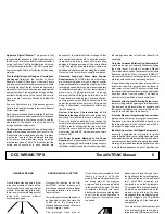
Appoint a Digital “Master” This person is fully
responsible for all aspects of the digital design for
the Show, and for setup and for digital operations
during the Show. The Digital Master and his crew
must be thoroughly familiar with DCC equipment,
its problems and solutions for the layout size being
planned.
Plan the Digital Layout Design as Carefully as
the Layout Determine the number of Power
Boosters, Radio/IR Receivers, Universal Panels
and amount of LocoNet cable necessary to handle
the configuration of the layout and the operations
planned for the Show. Know who is supplying what
equipment (if not Club-owned) and when it will be
available during setup of the layout. Be sure to
have a spare Command Station and Radio/IR
Receiver.
If you run lighted cars (e.g. Kato passenger cars)
be sure to include their current draw in any Booster
current calculations.
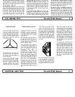
Each booster will need its own isolated "block" and
it's good practice to add a separate fast response
circuit breaker so a short does not shut down the
whole layout. The benefit is that you do not risk
frying expensive rolling stock.
Don't forget the coin test! It's a good idea to think
ahead of what happens when a short occurs! The
first test after the modules and all wiring is in place
must be the "coin test". Short between rails close
to the power source (booster) and then on the
most distant piece of track. This checks that the
wiring and connections in each section are
adequate 1) to maintain sufficient voltage so that
train control is not lost and 2) to allow the breaker
to trip should there be a heavy short, preventing
damage to N gauge equipment. If the coin test fails
to trip the breaker, a separate jumper cable may
be added parallel to the red wire along the modules.
Rerun the coin test until successfully completed.
Reversing Loops and Wyes Have Special
Requirements On NTRAK layouts where there
are no reversing loops or wyes, a single LocoNet
will generally work fine, handling everything. When
reversing loops and/or wyes are present separate
LocoNets are mandatory. Further, there must be a
ground wire (12 gauge preferred, 14 gauge
minimum) between the ground terminals on all
Power Boosters including the Command Station,
and this ground wire should be connected to the
power line ground at one point only. If the ground
wiring is insufficient, unpredictable effects are
likely to show up.
Review Electrical Characteristics of All
Modules in the Layout This is extremely important,
especially for modules that have not been in a
Show with digital operations. Even though the
owner may state categorically that he followed the
NTRAK rules for wiring modules, this may not be
sufficient to ensure trouble free digital operation -
what works fine with DC will sometimes not work
well with DCC.
Use Power Supplies Matched to the Power
Boosters Do not use standard DC power packs of
any type to supply Power Boosters. Always ensure
the power supply is capable of producing at least
the rated power output of the Power Booster it is
supplying.
Only One Command Station Can Command Be
sure there is only one Command Station controlling
the entire layout. Any other Command Station/
Power Boosters used on the layout must be set to
Booster-only mode. When the layout is REALLY
big, the whole layout must be separated into two or
more layouts linked with interchange blocks.
It is good operating practice when a locomotive or
locomotive consist is removed from the layout to
also remove it from the DCC system - break down
the consist to its individual locomotives and dispatch
each locomotive from the system. This frees up
slot memory for additional new locomotives.
Stress Test the Layout Following Setup Always
test everything before beginning normal operations.
Run as many single locomotives as possible over
the layout simultaneously. Some problems can
only be found with high traffic density.
Provide a Means of Programming Locomotives
Always have some way to program locomotives.
Someone may have just installed a decoder, or
there may be a need to check the values of CVs in
a decoder to diagnose a problem.
Identify Ownership of All Digital Equipment To
ensure the equipment is returned to its rightful
owner after the Show is over, all digital components
and equipment should be labeled with the owner’s
name or some other well-known clearly identifiable
marking. A return address label applied to the item
is a simple and adequate means of identification.
GENERAL DESIGN
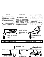
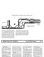
From the track planning point of view
a junction module consists of two
corner modules linked by a straight
module. If the planning grid is kept,
there is no problem closing several
loops with junctions without
scrunching any gap.
GORDONSVILLE JUNCTION
Gordonsville Junction is the first
oNeTRAK junction module and
provides an example of how to adapt
a prototype location to a modular
layout system.
The prototype Gordonsville has been
an important rail junction since the
1850s when the Orange and
Alexandria made a connection there
with the Virginia Central.
The prototype track plan at
Gordonsville is relatively simple. The
conventional wye has tracks heading
north to Alexandria, south to
Richmond
and
west
to
Charlottesville. Today, only one
additional track, a siding along the
north-south leg, still stands. A brick
tower, no longer used, stands at the
west end, and the center of the wye
contains the abandoned C&O water
tower which is used for storage by
the
city
of
Gordonsville.
Gordonsville's main street cuts
diagonally through the wye. The west
leg passes over the street on a low
girder bridge, allowing a view of 19th
century business structures from the
rails.
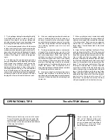
It took a few compromises to fit the
track on a four-foot by 30-inch
module. The west wye switch sits on
the wrong side of the highway
overpass, and the remaining siding
to the outside of the wye. The track
is isolated electrically into seven
blocks which are connected together
to suit the layout configuration. In
most cases, no reverse loop wiring
is needed.
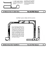
The minimum size of a juncion is 3
by 5 feet. The minimum radius can
be met and there's even space for
curve easements.
As the wiring of a junction involves
the reverse loop problem it is good
practice to have all three approaching
tracks on separate circuits. By
throwing switches the current
scheme of traffic then can be aligned.
One of the features of the track plan
is that the module can function in
several different configurations:
Junction (the usual mode); Corner;
Straight; and Branch line connection.
Because we forced the wye into a
four-foot length, the curved legs have
an effective radius of two and a half
feet. oNeTRAK modules are
designed in even foot increments.
This means that six inches needs to
be made up somewhere when the
module is part of a loop. We have
managed so far by making temporary
six-inch bridges out of Styrofoam
and by building a 2.5-foot module to
compensate.
To come out even, the module ought
to be five feet by three feet, which is
large for a oNeTRAK element. North
Raleigh NTRAK has built some three
track Junction modules in two
sections, which could work for
oNeTRAK as well. If the module
were this size, in one or two sections,
there would be room for a couple of
industries. A run-around track would
also help to make operations more
interesting.


