The oNeTRAK Manual
The oNeTRAK Manual
MAIN LINE JUNCTION
9
SWITCH WIRING TIPS
8
II
I
III
IV
V
2
1
2
3
1
5
1
4
2
2
3
1
4
5
4
5
7
9
8
6
7
9
8
6
2
3
1
2
3
1
R <-> N
R <-> N
1
8
5
4
2
1
2
9
7
6
3
3
3
R <-> N
1
8
2
9
7
6
3
R <-> N
Hand Thrown
or
Simple Wiring
Switch Motor
with
Frog Feeder
Switch Motor with
Frog Feeder and
Stop Block
Switch Motor with
Frog Feeder and
Power Selection
Switch Motor with
Frog Feeder,
Stop Block, and
Power Selection
Next
Block
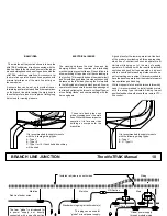
1 and 2 are the feeder wires for this portion of track
unless otherwise stated.
All switches are solid or electrofrog type.
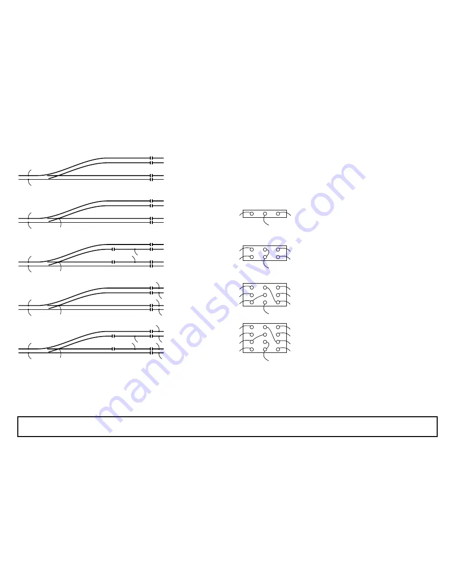
WIRING TYPES
For any discussion about junction, siding or yard
wiring it might be useful to get some sort of
common wiring schemes for individual switches.
Any type is used with Electrofrog Turnouts with
power routing through the switch tongue. Type I is
the standard case with hand thrown turnouts;
Type II - V are most likely used with switch motors.
The switch contacts will require a fixed mechanical
connection with the turnout tongue or unpredictable
results will occur (spelled short circuit).
WHAT TYPE TO USE
This part is not to be understood as a MUST USE
but rather as a help to decide which type best suits
your demand. More complicated schemes will
later help simplify the use of your module during
operation.
The stop block will help during more automatic
operations to stop trains more safely (as with
scheme I), as there cannot be a short when
approaching a closed turnout. Schemes III and V
are mainly for reverse loop or wye wiring. Special
care must be taken that under no circumstances
do two power supplies feed the same portion of
track (or any portion of track or wiring in between),
or the 'weaker' supply might fry!
N is the straight position of the switch and the
middle contacts are connected with the ones on
the right. R is the reverse or turnout position of the
switch and the left and middle contacts are
connected.
BASIC IDEA
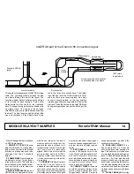
A oNeTRAK Mainline diverging from the Red Line
of a standard modules division is basically done
with a standard Junction module and a three to
one track transition module.
These Junction modules have been around for
quite a while and have been mainly used to link two
divisions' red line making up what Northern Virginia
NTRAK called the "Red Line Route".
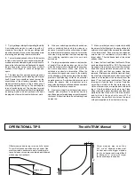
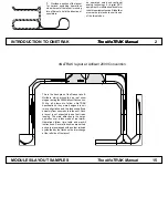
When an extension of a loop is desired either two
junction modules can be used (as seen on the
right), or a combination of a junction module with
a special module like Gordonsville is needed (as
seen on the track plan on page 14).
A
P
P
P
P
P
P
B
C
A
B
C
A
B
C
D
E
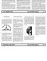
Module can be as short as
2' (610 mm)
A double line is a block boundary and a single line separates a
stop block. P indicates a connection with a power supply.
It is recommended to supply turnouts with the following wiring types:
A, B: Type III if power supply at both ends, otherwise a V might be used
C: Type III D,E: Type V
Add standard modules
to fit layout space
OPERATIONS
A single direction loop style scheme will not require
any manipulations during operations. Trains follow
each other and are guided either by tower
operators, by block indicators or over radio by a
dispatcher. Turnouts and electrical routing are
preset and need not be remotely controlled.
A more complex scheme permits individual routing
of the trains and therefore the turnouts of the
junction will be switched frequently. Remote control
and automatic electric routing helps prevent
mistakes and simplifies the work of the tower
operator.


