background image

(Revised 2011-09-02) 

11 

N-TRON 100-POE4 MID-SPAN POE GROUNDING TECHNIQUES 


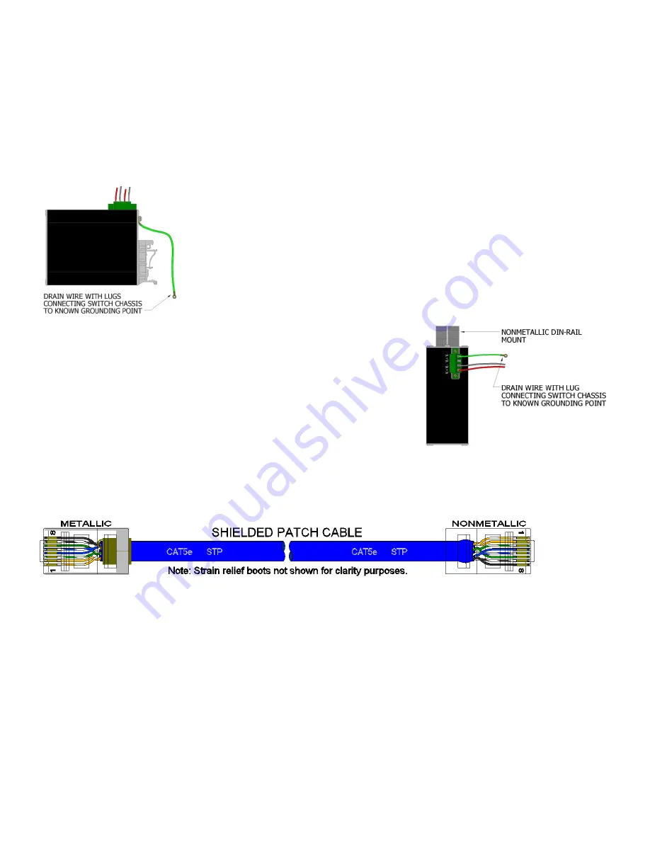
The grounding philosophy of any control system is an integral part of the design.  N-Tron switches are designed 
to  be  grounded,  but  the  user  has  been  given  the  flexibility  to  float  the  switch  when  required.    The  best  noise 
immunity and emissions (i.e. CE) are obtained when the N-Tron switch chassis is connected to earth ground via 
a drain  wire.  Some N-Tron switches  have metal  din-rail brackets  that can ground the switch if the din-rail is 
grounded.  In some cases, N-Tron switches with metal brackets can be supplied with optional plastic brackets if 
isolation is required. 

 
Users may run a drain wire & lug from the screw provided on the back face of the 
enclosure.   In the event the provided grounding screw has been lost, care should 
be taken to limit the penetration of the outer skin by less than 1/4".  Failure to do 
so may cause irreversible damage to the internal components of the switch.  
 
Note: Ensure the power supply is grounded properly before applying power to the 
grounded  switch.    This  may  be  verified  by  using  a  voltmeter  to  determine  that 
there is no voltage difference between the power supply’s negative output terminal 
and the chassis grounding point of the switch.   


As  an  alternative  grounding  method,  both  V-  legs  of  the  power  input 
connector are connected to chassis internally on the PCB.  Connecting 
a  drain  wire  to  earth  ground  from  one  of  the  V-  terminal  plugs  as 
shown here  will ground  the switch and the  chassis.   The power leads 
from the power source should be limited to 3 meters or less in length. 


If the use of shielded cables is required, it is generally recommended to only connect the shield at one end to 
prevent  ground  loops  and  interfere  with  low  level  signals  (i.e.  thermocouples,  RTD,  etc.).    Cat5e  cables 
manufactured to EIA-568A or 568B specifications are required for use with N-Tron Switches.  


In  the  event  all  Cat5e  patch  cable  distances  are  small  (i.e.  All  Ethernet  devices  are  located  the  same  local 
cabinet and/or referenced to the same earth ground), it is permissible to use fully shielded cables terminated to 
chassis ground at both ends in systems void of low level analog signals. 


Summary of Contents for 100-POE4

Page 1: ...Revised 2011 09 02 1 100 POE4 Unmanaged Industrial 4 Port Mid Span POE PSE User Manual Installation Guide...

Page 2: ...Revised 2011 09 02 2 Industrial 4 Port Mid Span POE PSE Installation Guide 100 POE4...

Page 3: ...ion contained in this document is subject to change without notice N TRON Corp makes no warranty of any kind with regard to this material including but not limited to the implied warranties of merchan...

Page 4: ...ing else to the unit Units not properly grounded may result in a safety risk and could be hazardous and may void the warranty See the grounding technique section of this user manual for proper ways to...

Page 5: ...RNING Explosion Hazard Do not remove or replace the device unless power has been switched off or the area is known to be non hazardous 5 Use 60 75 C rated Copper wire 0 22Nm 2 inch lbs Tightening torq...

Page 6: ...ttery backup for all these devices Key Features Compact space saving package IEEE 802 3af Compliant Four 10 100Base TX RJ 45 Ports DATA IN Four 10 100Base TX RJ 45 POE Ports DATA POWER OUT Unmanaged o...

Page 7: ...the equipment from the packaging and store the packaging in a safe place File any damage claims with the carrier CLEANING Clean only with a damp cloth INSTALLATION Read the following warnings before b...

Page 8: ...o remove the unit from the 35mm industrial DIN rail place a flat head screwdriver into the release clip found at the bottom of the unit and apply downward force on the clip until it disengages from th...

Page 9: ...rce of power V2 POE is being applied on the respective port with V2 as a valid source of power LEDs The table below describes the operating modes Port LEDs are for power supply status only and do NOT...

Page 10: ...wires have been secured to the 100 POE4 WARNING Inserting the input plug while the 48VDC is applied may cause arcing and damage the input connector permanently Verify the Power LED stays ON GREEN Not...

Page 11: ...is grounded properly before applying power to the grounded switch This may be verified by using a voltmeter to determine that there is no voltage difference between the power supply s negative output...

Page 12: ...Revised 2011 09 02 12 RJ45 CONNECTOR CRIMP SPECIFICATIONS Please reference the illustration below for your Cat5 cable specifications...

Page 13: ...to the Ethernet port the power does not boost data on the lines TROUBLESHOOTING 1 Make sure the Power LED is ON 2 Make sure you are supplying sufficient current for the 100 POE4 and all the powered de...

Page 14: ...cause harmful interference in which case the user will be required to correct the interference at his own expense INDUSTRY CANADA This Class A digital apparatus meets all requirements of the Canadian...

Page 15: ...isted for use in Class I Div 2 Groups A B C D T4A EMI EN 61000 6 4 EN 55011 Class A FCC Title 47 Part 15 Subpart B Class A ICES 003 Class A EMS EN 61000 6 2 IEC 61000 4 2 ESD IEC 61000 4 3 RS IEC 6100...

Page 16: ...Inrush Current 27 Amp 1 5 ms 48VDC under full load 24 Amp 1 5 ms 48VDC under no load Input Ripple Less than 100 mV Input Wire Size 20 10 AWG Environmental Operating Temperature 40 C to 85 C Storage Te...

Page 17: ...RANTIES EXCLUSIVE IF AN N TRON PRODUCT DOES NOT OPERATE AS WARRANTED ABOVE CUSTOMER S SOLE REMEDY FOR BREACH OF THAT WARRANTY SHALL BE REPAIR REPLACEMENT OR REFUND OF THE PURCHASE PRICE PAID AT N TRON...

Reviews: