background image

(Revised 2010-7-30) 

12 

Applying Power (Side View) 


Unscrew & Remove the DC Voltage Input Plug(s) from the side header 
Install the DC Power Cables into the Plug(s) (observing polarity). 
Plug the Voltage Input Plug(s) back into the side header. 
Tightening torque for the terminal block power plug is 

0.22 Nm/0.162 Pound Foot

All LED‟s will flash ON Momentarily 
Verify the Power LED stays ON (GREEN). 


Note:

  Only 1 plug must be connected to power for minimal operation.  For redundant power operation, 

V

1

 and V

2

 plugs must be connected to separate DC Voltage sources.  Use wire sizes 16-28 gauge.  The 

power cord should be limited to less than 10 meters in order to ensure optimum performance. 


Recommended 24V DC Power Supplies, similar to 100VAC/240VAC: 

 
N-Tron‟s NTPS-24-1.3, DC 24V/1.3A.  


Summary of Contents for 308FX2

Page 1: ...Revised 2010 7 30 1 308FX2 309FX 316TX 317FX Industrial Ethernet Switches User Manual Installation Guide...

Page 2: ...13 RJ45 Connector Crimp Specifications 14 Connecting the Unit 14 Serial Interface 15 Troubleshooting 15 Command Line Interpreter 17 Logging In password protection 18 CLI Tree of Menus 19 CLI Menus and...

Page 3: ...products 308FX2 N XX 308FXE2 N XX YY 309FX N XX 309FXE N XX YY 316TX N 317FX N XX 317FXE N XX YY Where N N for N ViewTM Blank Otherwise XX ST or SC and YY 15 40 80 Note The firmware version can be se...

Page 4: ...ncluded but not limited to lost profits arising out of errors or omissions in this manual or the information contained herein Warning Do not perform any services on the unit unless qualified to do so...

Page 5: ...ty when installing power input cables Reversing voltage polarity can cause permanent damage to the unit and void the warranty LASER SAFETY FXE 40 80 Only CAUTION CLASS 1 LASER PRODUCT Do not stare int...

Page 6: ...Revised 2010 7 30 6...
Page 7: ...e testing shall be considered 5 The end user shall provide bonding means as necessary All bonding equipment components shall be evaluated according to EN 60079 15 2005 and covered by a component certi...

Page 8: ...er optics The 316TX is an affordable 16 port copper port switch The 309FX 317FX is a 9 17 port switch that has 8 16 copper ports plus an additional multimode fiber optic up link port in the 309FX and...

Page 9: ...nd Flow Control Up to 2 6Gb s Maximum Throughput Industry Standard 35mm DIN Rail Enclosure Optional N ViewTM Monitoring on N units PACKAGE CONTENTS Please make sure the Ethernet Switch package contain...

Page 10: ...arts inside Removing the top cover will void the warranty DIN Rail Mounting Install the unit on a standard 35mm Din Rail Recess the unit to allow at least 5 of horizontal clearance for fiber optic cab...

Page 11: ...LED s located at the top or bottom of each connector The bottom LED indicates LINK status green for 100Mb link Orange for 10Mb link and the top LED indicates ACTIVITY Green for Full Duplex activity Or...

Page 12: ...lug is 0 22 Nm 0 162 Pound Foot All LED s will flash ON Momentarily Verify the Power LED stays ON GREEN Note Only 1 plug must be connected to power for minimal operation For redundant power operation...

Page 13: ...ed PEM nut to connect a ground lug via a machine screw care should be taken to limit the penetration of the outer skin by less than 1 4 in Failure to do so may cause irreversible damage to the interna...

Page 14: ...y other port to another Switch or Repeater use a standard Category 5 straight through or crossover cable Warning Creating a port to port connection on the same switch i e loop is an illegal operation...

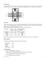
Page 15: ...male sub D connector for the 308FX2 309 316 317 end The following table shows the pin out and the connections for both types of cable PC Port 25 Pin 9 Pin 308FX2 309 316 317 Female Female 9 Pin Male S...

Page 16: ...in a residential installation This equipment generates uses and can radiate radio frequency energy and if not installed and used in accordance with the instructions may cause harmful interference to...

Page 17: ...HyperTerminal or equivalent COM Parameters 9600 8 none 1 none After a successful connection and reboot the boot menu should be displayed Self Test System Initialization Complete OK N TRON Industrial E...

Page 18: ...Self Test System Initialization Complete OK N TRON Industrial Ethernet Switch Model Number 308FX2 N N Tron firmware version 1 01 03 Copyright c 2010 N TRON MAC ADDRESS 00 07 AF 12 89 12 N View is ENA...

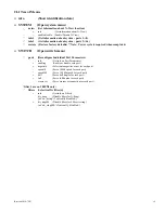
Page 19: ...Reconfigure Individual Port Parameters info Get info on Port Parameters enabling Enable or disable each port negotiate Select autonegotiate or not for each port speed10 Force 10 Mb speed for each port...

Page 20: ...and Description Comment info Displays information about the switch Model Number firmware version MAC address and whether or not the N View function is enabled SYSTEM Opens the SYSTEM menu The SYSTEM m...

Page 21: ...every port Command Description Comment info Displays the current values of the switch settings MAC address Enabled or disabled disable or enable Enable Disable N ViewTM Choice is opposite of current...

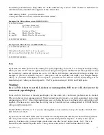
Page 22: ...ing factory defaults has these affects All ports are enabled All RJ45 ports are set for auto sensing All FX ports are set to 100 MHz and Full Duplex All RJ45 ports are set to auto MDIX as opposed to e...

Page 23: ...ll duplex and straight through wiring If you need half duplex also on port 2 you will have to select it also as auto sensing will be disabled for port 2 after you forced speed10 The FX ports are alway...

Page 24: ...crossover connection for each port Enter forced crossover ports Each time you select a forced port function speed duplex or crossover the ports you enter next are the complete new set of ports for th...

Page 25: ...e commas to separate port numbers Example 3 6 12 14 enter Enter Port Numbers or ESC to exit 5 CLI SWITCH PORTS Example of the Ports crossover screen CLI SWITCH PORTS crossover Enter forced crossover p...

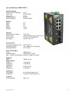
Page 26: ...mp 0 2 ms 24VDC Input Ripple Less than 100 mV Environmental Operating and Storage Temp 40oC to 85oC Operating Humidity 10 to 95 Non Condensing Operating Altitude 0 to 10 000 ft Shock and Vibration Sho...

Page 27: ...or Nonhazardous Locations only ATEX Zone 2 Category 3G II 3G Ex nA IIC DEMKO 03 ATEX 0316686U EMI EN61000 6 4 EN55011 Class A FCC 47 CFR Part 15 Subpart B Class A EMS EN61000 6 2 EN61000 4 2 ESD EN610...

Page 28: ...0 7ms 24 VDC Input Ripple Less than 100 mV Environmental Operating and Storage Temp 40oC to 85oC Operating Humidity 10 to 95 Non Condensing Operating Altitude 0 to 10 000 ft Shock and Vibration Shock...

Page 29: ...or Nonhazardous Locations only ATEX Zone 2 Category 3G II 3G Ex nA IIC DEMKO 03 ATEX 0316686U EMI EN61000 6 4 EN55011 Class A FCC 47 CFR Part 15 Subpart B Class A EMS EN61000 6 2 EN61000 4 2 ESD EN610...

Page 30: ...0 Amp 0 8 ms 24VDC Input Ripple Less than 100 mV Environmental Operating Temp 40oC to 85oC Storage Temp 40oC to 85oC Operating Humidity 10 to 95 Non Condensing Operating Altitude 0 to 10 000 ft Shock...

Page 31: ...CFR Part 15 Subpart B Class A EMS EN61000 6 2 EN61000 4 2 ESD EN61000 4 3 RS EN61000 4 4 EFT EN61000 4 5 Surge EN61000 4 6 Conducted Disturbances Conducted Low Frequency IEC60533 Shock IEEE 1613 250...

Page 32: ...0 A Inrush Current 8 5 Amp 0 8 ms 24VDC Input Ripple Less than 100 mV Environmental Operating and Storage Temp 40oC to 85oC Operating Humidity 10 to 95 Non Condensing Operating Altitude 0 to 10 000 ft...

Page 33: ...or Nonhazardous Locations only ATEX Zone 2 Category 3G II 3G Ex nA IIC DEMKO 03 ATEX 0316686U EMI EN61000 6 4 EN55011 Class A FCC 47 CFR Part 15 Subpart B Class A EMS EN61000 6 2 EN61000 4 2 ESD EN610...

Page 34: ...RANTIES EXCLUSIVE IF AN N TRON PRODUCT DOES NOT OPERATE AS WARRANTED ABOVE CUSTOMER S SOLE REMEDY FOR BREACH OF THAT WARRANTY SHALL BE REPAIR REPLACEMENT OR REFUND OF THE PURCHASE PRICE PAID AT N TRON...

Reviews: