background image

(Revised 2010-11-15) 


400 Series 

Industrial Ethernet Switches 


Installation 

Guide 


Summary of Contents for 405FX-SC

Page 1: ...Revised 2010 11 15 1 400 Series Industrial Ethernet Switches Installation Guide...

Page 2: ...Revised 2010 11 15 2 Industrial Ethernet Switch Installation Guide 405TX 405FX SC 405FX ST 405FXE SC YY 405FXE ST YY Where YY 15 40 or 80...

Page 3: ...limited to the implied warranties of merchantability or fitness for a particular purpose In no event shall N TRON Corp be liable for any incidental special indirect or consequential damages whatsoeve...

Page 4: ...the grounding technique section of this user manual for proper ways to ground the unit WARNING Do not work on equipment or cables during periods of lightning activity WARNING Do not perform any servi...

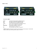
Page 5: ...The 405FXE is a 5 port unmanaged switch that is similar to the 405FX but with extended range The N TRON 405FXE utilizes a singlemode fiber transceiver that is capable of 15 Kilometers of 100 Mb commun...

Page 6: ...ation WARNING The 405FXE unit contains a Class 1 Laser Do not stare into the laser beam fiber optic connector when installing or operating the product Never install or work on electrical equipment or...

Page 7: ...lf Duplex Remove jumper In order to verify the jumper settings have been set correctly for units which have the N View option turned on you should install N ViewOPC Server software on a PC connected t...

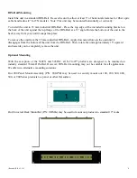
Page 8: ...t from the 35 mm industrial DIN Rail Apply downward force to the unit until it disengages from the bottom of the unit from the DIN Rail Then rotate the unit approximately 15 upward and towards you to...

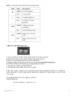
Page 9: ...FX FXE Only ACT Activity LED for Fiber Optic Port 405FX FXE only X RJ45 Crossover Uplink Port 405TX Only RJ45 Ports Auto sensing 10 100BaseT Connections Red LED indicates controller error Green LED li...

Page 10: ...the DC Power Cables into the Plug s observing polarity Plug the Voltage Input Plug s back into the side header Tightening torque for the terminal block power plug is 0 22 Nm 0 162 Pound Foot All LED s...

Page 11: ...users can run a drain wire lug from any of the Din Rail screws or empty PEM nuts on the enclosure When using an unused PEM nut to connect a ground lug via a machine screw care should be taken to limit...

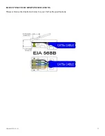
Page 12: ...Revised 2010 11 15 12 RJ45 CONNECTOR CRIMP SPECIFICATIONS Please reference the illustration below for your Cat5 cable specifications...

Page 13: ...ng a port to port connection on the same switch i e loop is an illegal operation and will create a broadcast storm which will crash the network TROUBLESHOOTING 1 Make sure the Power LED is ON 2 Make s...

Page 14: ...C to 85 C Operating Humidity 10 to 90 Non Condensing Operating Altitude 0 to 10 000 ft Network Media 10BaseT Cat 3 Cable 100BaseT Cat 5 Cable 100BaseFX Multimode 50 62 5 125 m Fiber Singlemode 7 10 1...

Page 15: ...us Locations or Non hazardous locations only EMI EN55022 Class A FCC Part 15 Class A EMS EN55024 1998 EN61000 4 2 1995 EN61000 4 3 1997 EN61000 4 4 1995 EN61000 4 5 1995 EN61000 4 6 1996 GOST R Certif...

Page 16: ...RANTIES EXCLUSIVE IF AN N TRON PRODUCT DOES NOT OPERATE AS WARRANTED ABOVE CUSTOMER S SOLE REMEDY FOR BREACH OF THAT WARRANTY SHALL BE REPAIR REPLACEMENT OR REFUND OF THE PURCHASE PRICE PAID AT N TRON...

Reviews: