23
All rights reserved ©N1 Critical Technologies, Inc.
NE Series (20-30kVA)
User Manual
Chapter 3 Installation
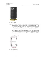
Step 5 Connect the parallel communicating connector of each paralleled UPS by parallel cables
(shielding communication wire), and fasten the corresponding parallel communicating
connector by bolts.
----End
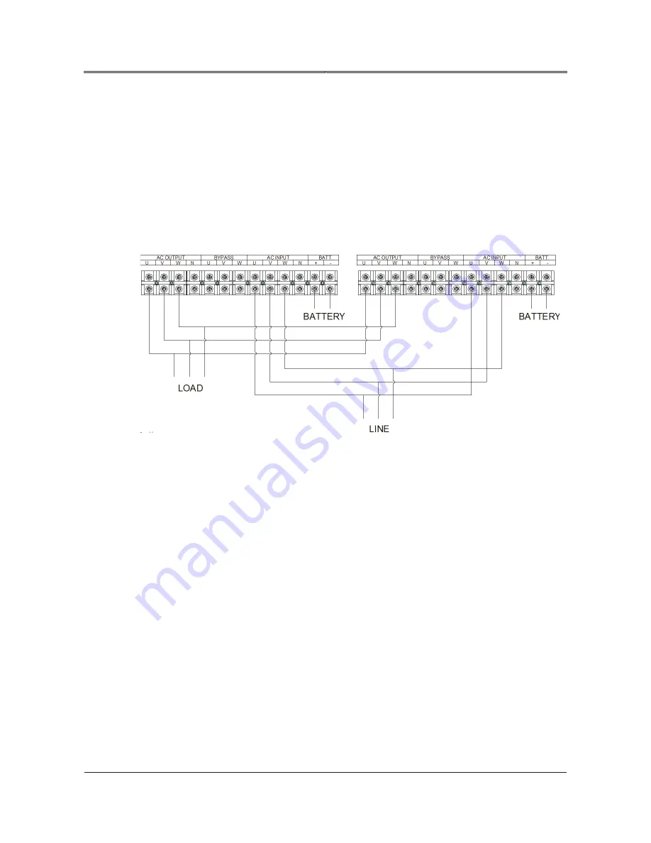
The lead of UPS 1’s and UPS 2’s output N, U, V, W are from the terminal bar of UPS, and short
circuited on load or distribution cabinet of load. The connection of parallel system is as shown in
Figure3-8.
Figure3-8 The terminal wiring of NE Series (20-30kVA) UPS
3.9 Connect Communication Wires
3.9.1
RS232 Communication
The RS232/RS485 communication port is located in the rear of the device. It can realize the remote
monitoring for input voltage, frequency, output voltage, frequency, load, etc. of the UPS, and it also
can achieve remote power on/ off operation.
Definition for RS232 pins:
DB9(RS232/485): 6P, RXD of UPS;
DB9(RS232/485): 7P, GND;
DB9(S232/485): 9P, TXD of UPS.
Summary of Contents for NE Series
Page 1: ...User Manual NE Series 20 30kVA...
Page 2: ......


