background image

62

All rights reserved ©N1 Critical Technologies, Inc.

NE Series (20-30kVA)

User  Manual

Chapter 4 Operation Guide

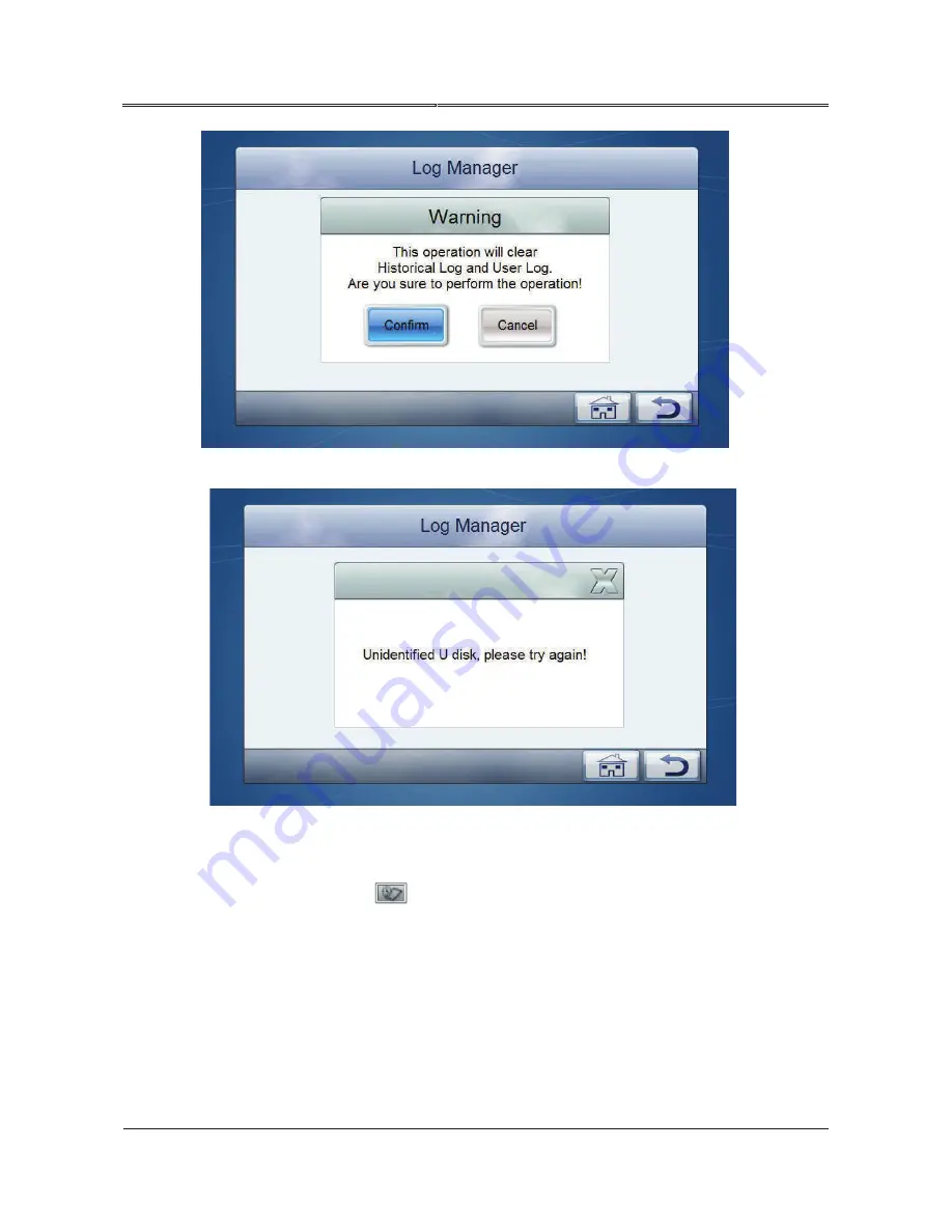
Figure4-50 Prompt for clearing log

Figure4-51 The U dish is not inserted

4.6.7

Information Inquiry

On monitoring page, click   

  icon to enter 

Information Inquiry 

page, the related information is 

as shown in Figure4-52.

Summary of Contents for NE Series

Page 1: ...User Manual NE Series 20 30kVA...

Page 2: ......

Page 3: ...of the products services and features described in this document may not be within the purchase scope or the usage scope Unless otherwise specification in the contract all statements information and r...

Page 4: ...to comply with safety matters during installation operation and maintenance Safety symbol meaning as follows Symbol Description Alerts you to a high risk hazard that could if not avoided result in ser...

Page 5: ...anual Foreword iii All rights reserved N1 Critical Technologies Inc Change History Changes between document issues are cumulative The latest document issue contains all the changes made in earlier iss...

Page 6: ...de 8 2 3 3 Work Principle for Series Hot Standby 9 2 4 Appearance and Panel 10 2 4 1 Appearance 10 2 4 2 Panel 10 Chapter 3 Installation 13 3 1 Unpacking and Checking 13 3 2 Environment 13 3 3 Tools14...

Page 7: ...e Electrical Connection 27 4 1 2 UPS Testing 28 4 2 Precautions for Operating UPS 28 4 3 Operation 29 4 3 1 Check Before Power on 29 4 3 2 Start the UPS 30 4 3 3 Start Load 30 4 3 4 Shutdown UPS 30 4...

Page 8: ...67 5 2 Periodic Preventative Maintenance 67 5 3 Battery Maintenance 68 5 3 1 Precaution for Battery Charging 68 5 3 2 Battery Maintenance 68 5 3 3 Battery Replacement 68 5 4 Fan Maintenance 69 Chapte...

Page 9: ...of different brands and different types of batteries may vary Make sure that the charging voltage of UPS and battery match If any doubt exists please consult the manufacturer for support Any change o...

Page 10: ...on of battery must be tight It is prohibited to touch the battery s two wire connectors or bare wire terminals or it may damage the battery and or endanger life 9 Prevent the battery electrolyte from...

Page 11: ...rist strap is well grounded Installing and removing power cables with AC input are prohibited Please turn off mains switch before connecting or removing power cables Before connecting the cable make s...

Page 12: ...ects are in front of air in and air out holes and fans to keep good ventilation When used in a residential building additional measures should be took to prevent tampering When UPS is disconnected it...

Page 13: ...kVA P means the UPScan beconnectedinparallelsystem If there is no P in the model number the unit is NOT able to be connected in parallel L means the UPS contains an internal long lasting Lithium Ion b...

Page 14: ...gn The UPS has an ECO energy conservation mode In this mode bypass output is prior and the efficiency of UPS is up to 97 when the voltage or frequency deviation of bypass is excessive UPS switches to...

Page 15: ...dundancy degree and convenient installation and debugging It can freely enter or exit the parallel system which achieves the online hot maintenance of parallel system LCD menu The large liquid crystal...

Page 16: ...temperature short circuit output voltage abnormal overload and surpasses the power range that the inverter can withstand the inverter will shut down automatically to prevent damage If the mains are s...

Page 17: ...f UPS 1 faults it will switch to bypass mode automatically At this moment the output of UPS 2 sustains the load which is still in UPS inverting protection status so as to ensure the safe operation of...

Page 18: ...er Manual Chapter 2 Overview 2 4 Appearance and Panel 2 4 1 Appearance The appearance of NE Series 20 30kVA UPS is shown in Figure2 4 Figure2 4 Appearance of NE Series 20 30kVA UPS 2 4 2 Panel The ope...

Page 19: ...e current load etc 2 BYPASS Bypass indicator Green Bypass output Red Bypass abnormal Light off Bypass normal but with no output 3 BATT Battery low voltage alarm indicator Red Battery abnormal alarm it...

Page 20: ...30kVA User Manual Chapter 2 Overview 7 ON System On combination button Press the two buttons simultaneously 8 OFF System Off combination button Press the two buttons simultaneously 9 EPO EPO button In...

Page 21: ...g damage is found report it to the carrier and your local dealer immediately Please provide photos of the UPS damage to us and we will offer corresponding service Check the delivery list to see if the...

Page 22: ...d resistance Label paper Used to prepare labels Phillips screwdriver 2 mm x 150 mm and 3 mm x 250 mm Used to tighten screws and bolts Slotted screwdriver 2mm 80mm Connect cable fasten screw Socket wre...

Page 23: ...panels and shells Brush Clean the panel and shell Heat shrink tubing 14 18 20 25 Used to insulate wires and conductors Heat gun Used to heat a heat shrink tubing Electrician s knife Used to strip cab...

Page 24: ...adjacent equipment at least 500mm from rear panel to he wall or adjacent equipment and at last 700mm from the top to ceiling which is to ensure good ventilation as shown in Figure3 1 Figure3 1 Install...

Page 25: ...Grounding wire cross section area mm 20 61 16 16 10 30 91 25 25 16 Table3 3 Selection for battery cables Power kVA Battery quantity Max current A Wire cross section area mm2 20 16 113 25 30 16 170 35...

Page 26: ...m the unit This is unique in every installation and the planning should be done by a qualified installation technician Move the UPS from the wooden packaging pallet to the ground before installing Ste...

Page 27: ...hen rotate the 4 support feet clockwise ensuring they go all the way up into the UPS This will put the weight of the device on the wheels Attach ramp in front of the UPS aligning it with the pallet Lo...

Page 28: ...tral wire of bypass do not need to connect with other wires The input neutral wire and output neutral wire share the same neutral wire terminal Step 1 Open the shrouding cover at the bottom of rear pl...

Page 29: ...Step 2 Dismantle the short connected bar between bypass switch and mains switch of UPS 1 and input neutral wire of UPS 1 Connect the three phase output live wire of UPS 2 to bypass switch of UPS 1 ac...

Page 30: ...n displays wrong phase sequence If the phase sequence is wrong when startup it is necessary to change them to correct status The connection phase sequence of each unit s AC input should be strictly in...

Page 31: ...of UPS and short circuited on load or distribution cabinet of load The connection of parallel system is as shown in Figure3 8 Figure3 8 The terminal wiring of NE Series 20 30kVA UPS 3 9 Connect Commun...

Page 32: ...monitoring for input voltage frequency output voltage frequency load etc of the UPS and it also can achieve remote power on off operation Definition for RS485 pins 5P of DB9 RS232 485 A 7P of DB9 RS2...

Page 33: ...remote control for power on off Before leaving factory the controlling wire of the UPS has been fixed on the installation port which marked with SNMP When installing it only needs to connect the contr...

Page 34: ...VA User Manual Chapter 3 Installation The anti reverse feedback device is built in to P Models only For the UPS models without built in anti reverse feedback device please check if there is dangerous...

Page 35: ...f 3 Confirm that there is no short circuit between input live line and input neutral line input live line and input ground line Confirm that there is no short circuit in output 4 Test the AC voltage o...

Page 36: ...tput at the same time the buzzer beeps slowly then disconnect the battery switch to simulate the status of protection for battery low voltage the UPS will turn to bypass output and the buzzer beeps co...

Page 37: ...acity does not exceed the rated output capacity of UPS or it will cause the protection for overload The calculation of load capacity is as follows The load capacity of NE series UPS is designed as 90...

Page 38: ...tecting board of battery polarity is off and the buzzer is silent and then close the battery switch of the UPS Step 4 Start the inverter system Press the ON combination buttons on the panel for 1S to...

Page 39: ...ctric power slowly about 5 minutes later the voltage will drop to a safe voltage To ensure safety only start maintenance to the UPS after 10 minutes Step 6 Disconnect the bypass input switch BYPASS Di...

Page 40: ...ads before starting parallel system completely Make sure all switches of parallel system s load are disconnected and all the input and output power lines are connected correctly Perform the following...

Page 41: ...Step 12 Step 8 Measure whether the output voltage difference of the UPS 1 and UPS 2 is normal If the voltage difference of the two UPSs is less than 10V it means the phase lock of the two UPSs in main...

Page 42: ...Parallel System Step 1 Close all loads Step 2 Close each inverter according to the shutdown steps of the UPS Step 3 Perform the shutdown steps of the UPS and disconnect the relative input and output s...

Page 43: ...h can enhance the reliability of the system When the load exceeds the above capacity the overload single unit more than N N 1 times rated output of single unit it will send alarm For example for the s...

Page 44: ...rsion HMI version device status User log Event records Information Working status Clear log backup log Restore default setting Password setting Date time backlight brightness backlight time language D...

Page 45: ...t abnormal the icon will flicker and show as Battery status If the battery abnormal the icon will flicker and show as Rectifying status If the rectifier fault the icon will flicker and show as Inverti...

Page 46: ...ll rights reserved N1 Critical Technologies Inc NE Series 20 30kVA User Manual Chapter 4 Operation Guide Figure4 6 Rectifier startup Figure4 7 Battery is not connected to load and the rectifier is sta...

Page 47: ...Technologies Inc NE Series 20 30kVA User Manual Chapter 4 Operation Guide Figure4 8 Rectifier inverting status load is on main power with battery now protecting the load Figure4 9 Battery inverting s...

Page 48: ...40 All rights reserved N1 Critical Technologies Inc NE Series 20 30kVA User Manual Chapter 4 Operation Guide Figure4 10 System bypass status Figure4 11 Rectifier bypass status...

Page 49: ...12 System maintenance bypass output Figure4 13 Protection for fault and with no output When the system occur abnormal condition the system will popup fault window at the same time there will be a faul...

Page 50: ...s 20 30kVA User Manual Chapter 4 Operation Guide Figure4 14 Now Fault window Figure4 15 Fault alarm indicator on Mains Information page After closing the current fault window click now fault indicator...

Page 51: ...ormation Click the button on Now Fault page to look up the event log information as shown in Figure4 17 Figure4 17 Event log information 4 6 4 Controlling Function ON OFF On main page click icon it wi...

Page 52: ...al Technologies Inc NE Series 20 30kVA User Manual Chapter 4 Operation Guide Figure4 18 On off interface 1 Figure4 19 On off interface 2 Click ON button it will enter confirmation interface click Conf...

Page 53: ...ologies Inc NE Series 20 30kVA User Manual Chapter 4 Operation Guide Figure4 20 Confirm to turn on When closing click OFF button it will enter confirmation interface click Confirm to perform shutdown...

Page 54: ...n to close open the buzzer When the buzzer is closed if there is new fault the buzzer will start again 4 6 5 Monitoring Function Bypass information On main page click icon it will enter Bypass Informa...

Page 55: ...click icon it will enter Mains Information interface as shown in Figure4 24 The page displays the phase voltage phase current and frequency of current system input mains Figure4 24 Mains information I...

Page 56: ...on On main page click icon it will enter Battery Information interface the displayed information is as shown in Figure4 26 Figure4 26 Battery information If the battery is not connected battery status...

Page 57: ...k icon it will enter output information interface as shown in Figure4 27 The page displays the phase voltage phase current frequency apparent power active power and load percentage Figure4 27 System o...

Page 58: ...n in Figure4 29 General user can look up each system parameter with no setting rights Maintenance expert can look up and set each parameter Figure4 29 Parameter setting interface System Management On...

Page 59: ...gure4 31 System management page 2 ECO mode on off ECO voltage upper threshold 10 15 ECO voltage lower threshold 10 15 After changing the parameter it is necessary to click button to save the setting I...

Page 60: ...c NE Series 20 30kVA User Manual Chapter 4 Operation Guide Figure4 32 Successful setting Figure4 33 Unsuccessful setting Battery management On parameters setting page click Battery Manage icon it will...

Page 61: ...range Click number input box it will display the input range of setting value at the top of the input keyboard when the setting exceeds the range the setting will be invalid After setting click button...

Page 62: ...Operation Guide Figure4 35 Battery test page Click Std Test icon it will popup confirming window click confirm to start standard test as shown in Figure4 36 Figure4 36 Standard test Click Deep Test i...

Page 63: ...ion Guide Figure4 37 Deep test After starting battery test the test status will show std test deep test as shown in Figure4 38 Figure4 38 Battery test During battery testing if it needs to stop testin...

Page 64: ...on Guide Figure4 39 Cancel battery test After finishing the battery test it will popup the battery test result as shown in Figure4 40 Figure4 41 Figure4 42 Figure4 43 shows the prompting window for ab...

Page 65: ...rights reserved N1 Critical Technologies Inc NE Series 20 30kVA User Manual Chapter 4 Operation Guide Figure4 41 Battery test result battery capacity low Figure4 42 Battery test result please check b...

Page 66: ...tore factory settings On Parameter Setting page click default setting icon it will popup confirmation window as shown in Figure4 44 Figure4 44 Restore to default setting After clicking Confirm button...

Page 67: ...0 30kVA User Manual Chapter 4 Operation Guide Figure4 45 Setting success prompting window Figure4 46 Setting failure prompting window Screen setting On Parameter Setting page click screen setting icon...

Page 68: ...system accurately Password setting On Parameter Setting page click password setting icon it will enter Password Setting page The current user s password can be changed only as shown in Figure4 48 The...

Page 69: ...nual Chapter 4 Operation Guide Figure4 48 Password setting Log manager On Parameter Setting page click log manager icon it will enter Log Manager page On the page you can clear log and user log Insert...

Page 70: ...20 30kVA User Manual Chapter 4 Operation Guide Figure4 50 Prompt for clearing log Figure4 51 The U dish is not inserted 4 6 7 Information Inquiry On monitoring page click icon to enter Information In...

Page 71: ...e Figure4 52 Information inquiry Work status On Information Inquiry page click working status icon it will enter Work Status page as shown in Figure4 53 Figure4 53 Work status If the battery is not co...

Page 72: ...On Information Inquiry page click event log icon it will enter Event Log page The page records the historical fault and alarm information of the system as shown in Figure4 54 Figure4 54 Event log User...

Page 73: ...n Inquiry page click product info Icon it will enter Product Info page the first page shows the product name model manufacturer contact information etc as shown in Figure4 56 Figure4 56 Product inform...

Page 74: ...ogies Inc NE Series 20 30kVA User Manual Chapter 4 Operation Guide When the probation is opened the device status shows as At this time user can click icon to enter probation unlock page After success...

Page 75: ...ther conductive metal ornaments Do not wear loose clothing Operate it in strict accordance with safety procedures If in doubt please consult a certified electrical technician to maintain your equipmen...

Page 76: ...en battery covers 5 3 2 Battery Maintenance To ensure a long battery lifespan perform the following maintenance tasks periodically Normally it needs to charge and discharge the battery once every 4 6...

Page 77: ...in the same capacity same type and same manufacturer It is strictly prohibited to use the battery with different capacity type and manufacturers Batteries that are replaced should be recycled 5 4 Fan...

Page 78: ...ouch screen displays wrong phase sequence the buzzer beeps continuously AC input phase is wrong Change the phase sequence of rectifier s mains input wires Generally it only needs to change two phases...

Page 79: ...the mains normal 7 LOAD indicator is on The output of UPS is overload Decrease the load 8 When power on normally it cannot output normally Check whether the bypass inverter SCR drive board is fault Pl...

Page 80: ...reverse connected or the three wires of the output are wrongly connected 3 After starting the UPS can output 110V AC power but the UPS works in bypass status The load capacity exceeds the rated outpu...

Page 81: ...the UPS when mains normal and charge for the battery 6 After the UPS starts to work for a while the buzzer beeps intermittently The voltage of grid is too low and the UPS works in battery inverting st...

Page 82: ...the user load and disconnect the input output switch of UPS which is to avoid further damage of the UPS Emergency for the fault of UPS 1 and UPS 2 in series backup system When the UPS 1 of the series...

Page 83: ...fety criterion and with the same character on the basis of corresponding rules The fuse fusing character and disjunction capacity of the fuse used in input end output end battery input end of this ser...

Page 84: ...on tracking range Hz 50 60 5 10 optional Bypass input voltage range V 20 15 15 20 25 Input power factor PF 0 99 Input current harmonic THDI 3 Phase 3 4W PE Battery voltage Vdc 167 224 Input Charging c...

Page 85: ...voltage input frequency three phase output voltage load battery voltage battery charging discharging current etc LED display Work status and alarm of UPS Alarm function Input abnormal battery under v...

Page 86: ...d storage temperature exceed the work temperature it is necessary to place the UPS to normal operation temperature environment and keep it for at least 4 hours before installing and powering on Altitu...

Page 87: ...rent DSP Digital Signal Processor E EMC Electromagnetic compatibility EPO Emergency Power Off ESD Electrostatic Discharge ESSD Electrostatic Sensitive Devices L LCD Liquid Crystal Display LED Light Em...

Page 88: ...80 All rights reserved N1 Critical Technologies Inc NE Series 20 30kVA User Manual B Acronyms andAbbreviations...

Reviews: