5 of 8
www.NabcoEntrances.com
GT1505BumpOutConvenienceWindowInstallationManual
Rev. 12-15-17
P/N C-00208
DN 1822
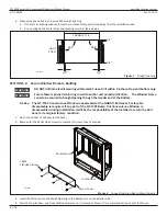
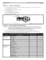
1/4" Shim and plumb
for proper clearance
OUTSIDE OF BUILDING
INSIDE OF BUILDING
Rough Opening
1/4" Shim and plumb
for proper clearance
Rough Opening
Figure 3
Shim and Plumb Window Frame
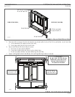
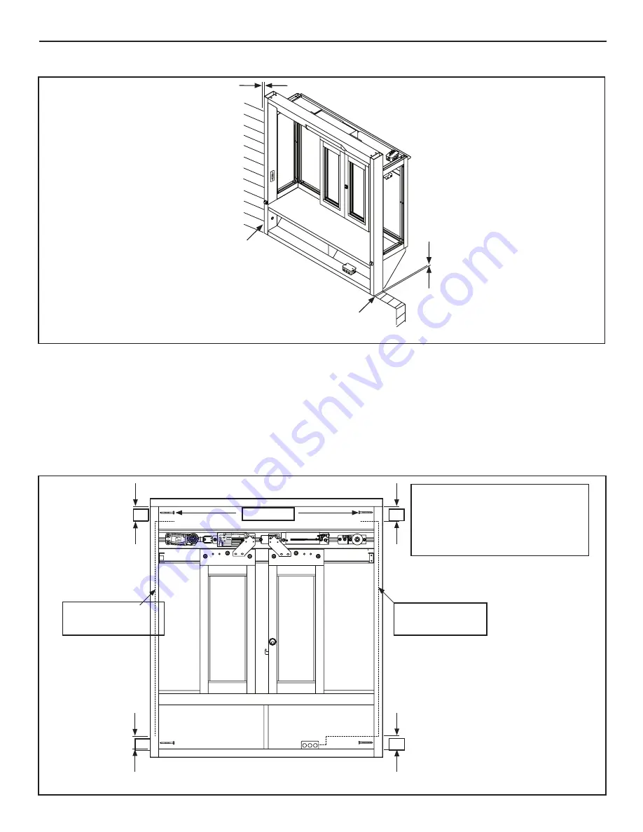
5. Mark and drill a minimum of (2), 1/4 inch diameter screw holes (within 3 inches) from the top and bottom in each Jamb Tube.
a. It is recommended to countersink each screw hole.
b. Use an appropriate tap drill to drill a pilot hole.
6. Secure Jamb Tubes with 1/4 inch diameter screws.
a. Fasteners are not provided by NABCO.
b. Ensure each visible screw head is flush on face of Jamb Tube.
c. Do not overtighten fasteners to prevent deforming the Jamb Tube.
7. Apply a caulking bead between the Window Unit and Rough Opening (inside and outside).
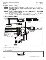
NABCO
24-11493
GYRO TECH
DS-150
NA
(
24-11327
)
MADE IN JAPAN
5 6
Sequential Activation
SQ
Auxiliary Output (Open-Collector)
5Amax.(0-20V), 3.2Amax.(20-30V)
30V(42.4Vpeak)max.
Contact Output (Class2 Load only)
N/C
N/O
12VDC-(Common)
FUNCTION [SLIDING DOOR]
SYMBOL No.
Reduced Opening Switch
7
6
5
4
3
2
1
Breakout Detector
Sidelite Presence Sensor
Exterior Activation
BA
62
M1
H
M0
Holding Beam
Interior Activation
12VDC-(Common)
12VDC+
6B
9DC12V
7
61
Mode Switch (see Mode SW Usage shown left)
HANDY TERMINAL
・
6P
To protect against risk of
fire
or electric shock,use only the
certified NABCO power supply.
WARNING
No.
MOTOR
・
12P
ERROR
POWER
BA
62
H
6B
61
IN
DI
CA
TO
RS
PO
W
ER
・
2P
Do not disassemble the control box.
There are no user serviceable parts
inside.
To maintain warranty,repairs must be
made by authorized NABCO facilities.
CAUTION
Adjustments to the door can only be made
with the NABCO Handy Terminal.
Mode SW Usage
Gnd
Gnd
Gnd
Open
Open
Open
Gnd
Open
M0
M1
MODE
TWO WAY
ONE WAY
NIGHT
HOLD OPEN
248901-
Microprocessor Controller
20
VA
C
50
/60
Hz
GYRO TECH
NABCO
24-11493
DN 1821
1/4” Screw
!!Electrical Wiring
inside Jamb Tube!!!
!!Electrical Wiring
inside Jamb Tube!!!
3”
3”
3”
3”
!! !! WARNING !!
DO NOT DRILL INTO ELECTRICAL
WIRING WITHIN JAMB TUBES.
DRILL WITHIN 3 INCHES AT
TOP AND BOTTOM ONLY.
Figure 4
Mark, Drill, and Secure Jamb Tubes


