6 of 8
GT1505 Bump Out Convenience Window Installation Manual
www.NabcoEntrances.com
P/N C-00208
Rev 12-15-17
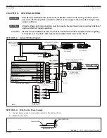
CHAPTER 6: GENERAL WIRING
Shut OFF the installation site, branch Circuit Breaker. Failure to do so may result in serious
personal or fatal injury. When uncertain whether power supply is disconnected, always verify
using a voltmeter.
All high voltage electrical connections must be made by licensed electricians according to National
and Local electrical codes/regulations .
Attention: Electrical circuit to Nabco operator must not be not shared with other equipment such as lighting,
cash registers, or any device that might cause electrical interference on the circuit .
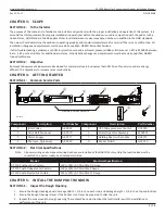
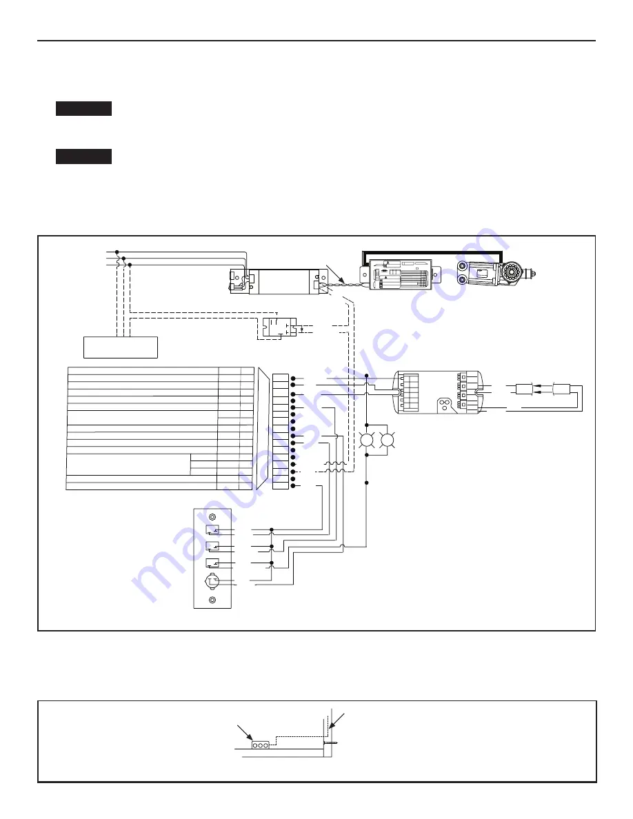
SECTION 6 .1: General Wiring Diagram
RED
DN 1882
Air Curtain
(Op onal)
5 6
12
13
14
15
16
Sequential Activation
SQ
Auxiliary Output (Open-Collector)
OUT
5Amax.(0-20V), 3.2Amax.(20-30V)
30V(42.4Vpeak)max.
Contact Output (Class2 Load only)
Common
N/C
N/O
OUT.A
OUT.B
OUT.C
12VDC-(Common)
7
FUNCTION [SLIDING DOOR]
SYMBOL No.
Reduced Opening Switch
11
10
9
8
7
6
5
4
3
2
1
Breakout Detector
Sidelite Presence Sensor
Exterior Activation
BA
62
SLS
M1
H
M0
Holding Beam
Interior Activation
12VDC-(Common)
12VDC+
6B
9DC12V
7
61
Mode Switch (see Mode SW Usage shown left)
HANDY TERMINAL
・
6P
RE
LA
TE
D
DE
VI
CE
S
・
16
P
To protect against risk of
fire
or electric shock,use only the
certified NABCO power supply.
WARNING
No.
MOTOR
・
12P
ERROR
POWER
BA
62
H
6B
61
IN
DI
CA
TO
RS
PO
WE
R
・
2P
Do not disassemble the control box.
There are no user serviceable parts
inside.
To maintain warranty,repairs must be
made by authorized NABCO facilities.
CAUTION
Adjustments to the door can only be made
with the NABCO Handy Terminal.
Mode SW Usage
Gnd
Gnd
Gnd
Open
Open
Open
Gnd
Open
M0
M1
MODE
TWO WAY
ONE WAY
NIGHT
HOLD OPEN
248901-
Microprocessor Controller
20
VA
C
50
/60
Hz
GYRO TECH
U30 POWER SUPPLY
P/N A-00717
U30 Control
P/N V-00020
Motor/Operator
P/N M-00395
U30 Control Relay
(Op onal)
Optex Holding Beam Controller
P/N A-00129
Optex Control (OS-12CT)
must be set to
Mode B (2 Flashes)
TERMINAL ON U30 CONTROL
P/N V-00410
LABEL ON U30 CONTROL
Rocker Switch
P/N A-01356
MAIN HARNESS
P/N A-01357
POWER SUPPLY HARNESS
P/N M-00412
GYRO TECH
DS-150
NA
(
24-11327
)
MADE IN JAPAN
12
13
14
15
16
Sequential Activation
SQ
Auxiliary Output (Open-Collector)
OUT
5Amax.(0-20V), 3.2Amax.(20-30V)
30V(42.4Vpeak)max.
Contact Output (Class2 Load only)
Common
N/C
N/O
OUT.A
OUT.B
OUT.C
12VDC-(Common)
7
FUNCTION [SLIDING DOOR]
SYMBOL No.
Reduced Opening Switch
11
10
9
8
7
6
5
4
3
2
1
Breakout Detector
Sidelite Presence Sensor
Exterior Activation
BA
62
SLS
M1
H
M0
Holding Beam
Interior Activation
12VDC-(Common)
12VDC+
6B
9DC12V
7
61
Mode Switch (see Mode SW Usage shown left)
RE
LA
TED DEVICE
S
・
16
P
DC OU
T
AC IN
G N
L
-
+
Optex OS-12C
T
Controlle
r
1
2
3
4
5
6
7
8
9
10
11
12
13
14
12
13
14
15
11
10
9
8
7
6
5
4
3
2
1
16
GREEN (Ground)
WHITE (Neutral)
BLACK (Hot)
BLAC
K
BLACK
RED/WHT
BROWN
BLACK
RED
GREEN
BLACK
BLUE
RED/WHT
RED
RED
RED
RED
RED
RED
BLACK
RED/BLACK
RED
LED
LED
BLUE
SHIELD RCVR
EMIT
SHIELD GRAY
BLACK
GREEN
RED/BLACK
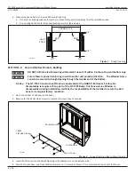
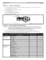
SECTION 6 .2: Wire Unit to Power Supply
1. Connect Branch wiring to Junction Box located at the bottom of Unit.
2. Replace Access Cover.
DN 1940
Bo om of Unit
Branch Wiring
Junc on Box
Figure 5
Wire Unit to Power Supply
WARNING
WARNING