63
NABRICO DF-1 N ELECTRIC WINCH Owner’s Manual
OM-DF1-021-A
MOTOR BRAKES
INSTALLATION & MAINTENANCE
RETAIN FOR FUTURE USE
U35000 - 9 of 19
www.nord.com/docs
06.13.16
NORD Gear Corporation
Toll Free in the United States: 888.314.6673
NORD Gear Limited
Toll Free in Canada: 800.668.4378
Brake Rotor (Brake Disc) Wear Assessment
Periodically the brake rotor or brake disc must also be checked
for wear. If the brake rotors wear approaches the minimum
allowed thickness, then the part should be replaced. Use
Table 7 to determine whether or not the brake rotor requires
replacement.
Table 7: Brake Rotor Thickness
Brake Size
Nominal Brake Rotor
Thickness
Minimum Brake Rotor
Thickness
[in]
[mm]
[in]
[mm]
BRE 5
0.295
7.5
0.177
4.5
BRE10
0.335
8.5
0.217
5.5
BRE20
0.406
10.3
0.295
7.5
BRE40
0.492
12.5
0.374
9.5
BRE60
0.571
14.5
0.453
11.5
BRE100
0.630
16
0.492
12.5
BRE150
0.709
18
0.571
14.5
BRE250
0.787
20
0.650
16.5
BRE400
0.787
20
0.650
16.5
BRE800
0.787
20
0.650
16.5
BRE1200
0.866
22
0.689
17.5
As new condition.
Worn condition - brake rotor replacement is required!
Brake Pad Replacement
(reference to parts list on page 8)
When the brake pad is worn the pad should be replaced to
maintain proper brake operation and ensure safety.
Required Tools
• Phillips head screw drivers (fan shroud removal)
• External snap ring pliers (fan and brake hub removal).
• Large flat head screw driver or small pry bar (fan removal)
• Metric T-handle wrenches and open-end wrenches.
Procedure
1. Remove the fixing screws (946) securing the fan cover (940)
to the motor end-shield (932). If the brake has a hand
release (937), the lever arm should be removed by
unscrewing it.
2. Remove the fan cover (940) and note the position of the
hand release slot if applicable.
3. Remove the snap ring holding the cooling fan (939) and
carefully remove the cooling fan (939), key and second
snap ring (997).
4. If the brake is equipped with a dust boot (992), remove it.
5. Remove the socket head cap screws holding the brake coil
(936) to the motor end-shield (932).
6. Remove the brake coil (936), noting the hand release (937)
and power cable locations.
7. Slide the brake rotor (993) off the brake hub (938) which is
secured to the motor shaft.
8. Clean the brake, install the new brake rotor pad and
reassemble the brake in reverse order of the steps outlined.
Optional Brake Accessories
NORD can supply a variety of brake options and accessories,
of which some of the most common are noted below.
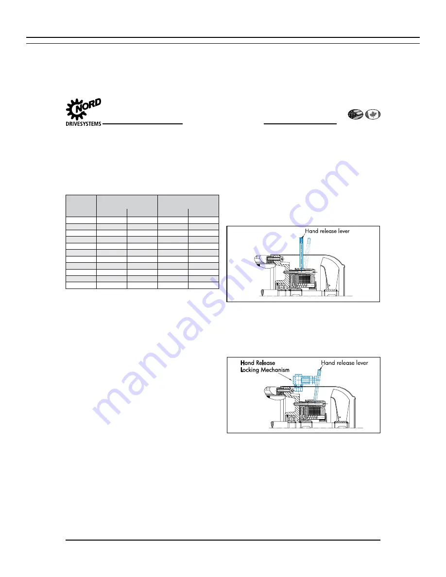
Hand Release Lever (HL)
The hand release lever allows the brake to be manually re-
leased without requiring that the brake be energized with
voltage. The lever has a spring return that allows the brake to
be hand released and returned automatically to its set posi-
tion. The handle of the hand release lever can be unscrewed
for easy removal.
Figure 8
Por Palanca de Liberación
Locking Hand Release Lever (FHL)
This option allows the brake to be manually released and
locked off without requiring voltage to the brake. The lock
mechanism prevents the spring from returning the brake to
a closed state without manual action by the user. The hand
release lever can be unscrewed for easy removal.
Figure 9
Por Palanca de Liberación
Liberación de mano
de mecanismo de
bloqueo
Corrosion Protected Brake (RG)
The brake is fitted with a stainless steel brake plate to pro-
vide additional corrosion protection in severe and wet envi-
ronments.
Dust & Corrosion Protected Brake (SR)
A rubber-sealing boot is installed on the brake to provide
additional protection in dusty environments. This feature in-
cludes the stainless steel brake plate (RG).
IP66 Brake (IP66)
NORD can also provide an IP66 brake option designed for
a bigger degree of protection against severe environments.
Summary of Contents for DF-1 N Series
Page 1: ...OM DF1 021 A NABRICO DF 1 N Electric Winch Owner s Manual ...
Page 2: ...THIS PAGE IS INTENTIONALLY LEFT BLANK ...
Page 21: ...21 NABRICO DF 1 N ELECTRIC WINCH Owner s Manual OM DF1 021 A ...
Page 22: ...22 NABRICO DF 1 N ELECTRIC WINCH Owner s Manual OM DF1 021 A ...
Page 23: ...23 NABRICO DF 1 N ELECTRIC WINCH Owner s Manual OM DF1 021 A ...
Page 25: ... A 25 NABRICO DF 1 N ELECTRIC WINCH Owner s Manual OM DF1 021 A ...
Page 26: ... 72 61 26 NABRICO DF 1 N ELECTRIC WINCH Owner s Manual OM DF1 021 A ...
Page 27: ... 1 1 2 3 Ω 27 NABRICO DF 1 N ELECTRIC WINCH Owner s Manual OM DF1 021 A ...
Page 28: ... 63 2 M4 Attachment 28 NABRICO DF 1 N ELECTRIC WINCH Owner s Manual OM DF1 021 A ...
Page 29: ... 1 1 1 1 1 1 2 2 2 2 29 NABRICO DF 1 N ELECTRIC WINCH Owner s Manual OM DF1 021 A ...
Page 31: ... 31 NABRICO DF 1 N ELECTRIC WINCH Owner s Manual OM DF1 021 A ...
Page 32: ... 1 1 1 1 2 2 2 2 3 3 3 3 32 NABRICO DF 1 N ELECTRIC WINCH Owner s Manual OM DF1 021 A ...
Page 36: ...36 NABRICO DF 1 N ELECTRIC WINCH Owner s Manual OM DF1 021 A ...
Page 69: ...69 NABRICO DF 1 N ELECTRIC WINCH Owner s Manual OM DF1 021 A ...
Page 70: ...70 NABRICO DF 1 N ELECTRIC WINCH Owner s Manual OM DF1 021 A ...


