60
NABRICO DF-1 ND ELECTRIC WINCH Owner’s Manual
OM-DF1-017-G
REDUCER MOUNTING
FOOTED & FLANGE MOUNT GEAR UNITS
RETAIN FOR FUTURE USE
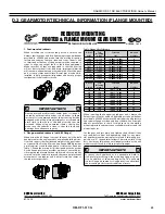
3. Flange-mounted reducers (with B14 flange)
When using the B14 flange to mount the gear unit, the bulk
head plate must be engineered to minimize buckling distor-
tions and support the cantilevered weight of the gear reducer
or gearmotor. When properly installed, the output flange of
the reducer housing is designed to enable the permissible
torques and radial forces to be reliably transmitted by the
bolt connections.
IMPORTANT NOTE
When using the B14 flange-face for mounting, if dowel
pin holes are provided in addition to the threaded holes,
then it is advisable to also use the proper dowel pins, to
help control flange movement or flange rotation and
relieve the mounting bolts from this additional stress
This is especially important for heavy shock applications.
4. Foot & flange reducer housings
Some gear reducer housings are available with a foot and an
output flange. Units with a foot and a B5 Flange are desig-
nated with the suffix XF after the primary model number and
units with a B14 face-flange are designated with the suffix
XZ after the primary model number. When a gear unit is
provided with both a foot and a flange, the foot is consider
the primary mounting surface. The flange is generally consid-
ered to be the secondary mounting option and it is intended
that this surface be used for auxiliary add on elements that
place minimal load stress on the reducer housing.
STOP
HARMFUL SITUATION
STOP
To prevent overstress on the main gear unit housing, never
tighten the reducer mounting feet and the mounting
flange against one-another. Auxiliary add-on elements
that are mounted to the reducer flange, must not transmit
excessive force, torque or vibration to the main gear
housing.
U10500 - 2 of 2
www.nord.com/docs
07.19.16
NORD Gear Corporation
Toll Free in the United States: 888.314.6673
NORD Gear Limited
Toll Free in Canada: 800.668.4378
Summary of Contents for DF-1 Series
Page 1: ...OM DF1 017 G NABRICO DF 1 ND Electric Winch Owner s Manual ...
Page 2: ...THIS PAGE IS INTENTIONALLY LEFT BLANK ...
Page 21: ...21 NABRICO DF 1 ND ELECTRIC WINCH Owner s Manual OM DF1 017 G ...
Page 22: ...22 NABRICO DF 1 ND ELECTRIC WINCH Owner s Manual OM DF1 017 G ...
Page 23: ...23 NABRICO DF 1 ND ELECTRIC WINCH Owner s Manual OM DF1 017 G ...
Page 25: ... A 25 NABRICO DF 1 ND ELECTRIC WINCH Owner s Manual OM DF1 017 G ...
Page 26: ... 72 61 26 NABRICO DF 1 ND ELECTRIC WINCH Owner s Manual OM DF1 017 G ...
Page 27: ... 1 1 2 3 Ω 27 NABRICO DF 1 ND ELECTRIC WINCH Owner s Manual OM DF1 017 G ...
Page 28: ... 63 2 M4 Attachment 28 NABRICO DF 1 ND ELECTRIC WINCH Owner s Manual OM DF1 017 G ...
Page 29: ... 1 1 1 1 1 1 2 2 2 2 29 NABRICO DF 1 ND ELECTRIC WINCH Owner s Manual OM DF1 017 G ...
Page 31: ... 31 NABRICO DF 1 ND ELECTRIC WINCH Owner s Manual OM DF1 017 G ...
Page 32: ... 1 1 1 1 2 2 2 2 3 3 3 3 32 NABRICO DF 1 ND ELECTRIC WINCH Owner s Manual OM DF1 017 G ...
Page 36: ...36 NABRICO DF 1 ND ELECTRIC WINCH Owner s Manual OM DF1 017 G ...

