Chapter 4 Preparations for Installation
16
Handling bolt size/Hollow shaft series
Table 4-6
Model code
Handling bolt
Nominal size × pitch
(mm)
Qty.
Weight (kg)
Straight*1
Right angle*1
Pulley
RD -010C
-
-
10 to 22
12 to 23
10
RD -027C
M6 × 1.0
4
17 to 28
18 to 30
16
RD -050C
M8 × 1.25
4
30 to 42
33 to 45
29
RD -100C
M10 × 1.5
4
38 to 50
41 to 53
37
RD -200C
M12 × 1.75
4
96 to 112
118 to 134
94
RD -320C
M12 × 1.75
4
141 to 158
164 to 180
140
*1: The weight varies depending on the coupling inner diameter of the input unit and the motor flange type.
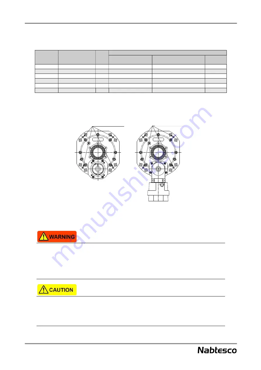
<For RD -027C, 050C, 100C, 200C, and 320C>
For the straight input type and
pulley input type
Right angle input type
Fig. 4-6
Do not enter the area under the reduction gear when lifting the reduction gear. If the reduction gear
falls down, it could cause injury.
When lifting the
reduction gear
, be sure to use a lifter that can withstand the weight of the reduction
gear. Otherwise, the lifter will be damaged, and the reduction gear could fall down and topple over,
which may result in injury.
Be sure that no load is applied to the hollow section when lifting. The reduction gear could be
damaged and the components could fall down, which may cause injury to the workers. In addition, the
oil seals for the hollow section may be deformed, which could eventually cause leakage of the
lubricant.
Tapped hole for
handling bolt
Tapped hole for
handling bolt
(4 locations)
(4 locations)


