background image

23

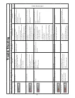
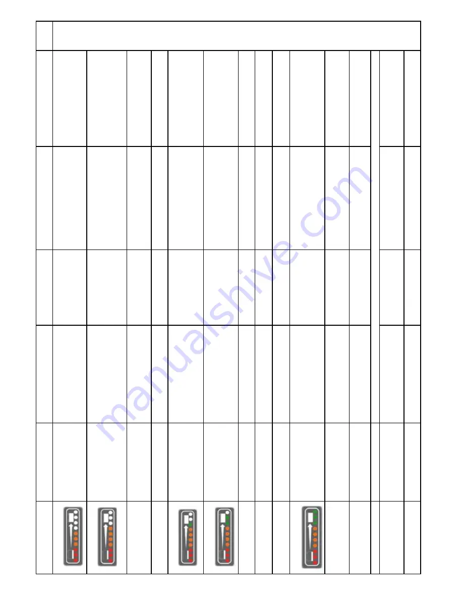
Number of bars flashing on display

Fault

Possible Cause

Ef

fect on Product

Investigate the Following

Action Required

If Fault 

Persists.

* 6 Bars flash continuously

.

* Control system is Inhibiting drive.

* Faulty controller

.

* Machine will not operate.

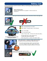
* Check controller for water damage.

* Replace controller

.

*7 Bars flash once with pause

* Accelerator pedal trip.

* Accelerator pedal being activated without 

seat switch being activated (nobody on seat) 

Or seat switch momentarily deactivated while 

accelerator pedal being activated during forward 

/ reverse operation.

* Machine will not drive.

* Ensure accelerator pedal is not activated without  

seat switch being activated. Ensure firm contact 

with seat by operator at all times while accelerator 

is pressed.

* Operator to be trained.

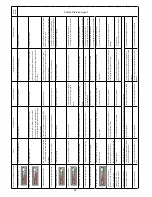
* 7 Bars flash twice with pause.

“ Emergency stop has been activated.

* Of

f aisle cleaning activated with floor 

tool raised.

* Inadvertent pressing of emergency stop or 

activation of of

f-aisle cleaning mode.

* Machine will not drive.

* Ensure emergency Stop button has not been 

activated and of

f aisle vac switch is in of

f position 

with floor tool raised.

* Reset emergency stop button. Switch of

f aisle 

vac and raise floor tool.                  

* Cycle key switch to resume normal operation.

* 7 Bars flash 3 times with pause.

* V

ac Motor system short circuit.

* V

ac motor wiring fault / motor fault.

* V

ac motor will not operate.

* Check vacuum motor and wiring

* Replace motor and any damaged wiring. 

* Cycle key switch to resume normal operation.

* 8 Bars flash continuously

.

* Control system trip.

* Seat switch failure.

* Machine does not operate.

* Check seat switch wiring.

* Replace wiring as required.

* 9 Bars flash once with pause.

* Flashing beacon failure to operate.

* Beacon short circuit.

* Flashing beacon does not operate 

in accordance with safety require

-

ments.

* Check wiring and connections to device.

* Replace damaged components.

* Cycle Key switch to resume normal operation.

* 9 Bars flash 3 times with pause.

* W

ater pump failure to operate.

* Failure of pump or wiring short circuit.

* No water supplied to cleaning 

heads.

* Check wiring and connections to pump.

* Replace damaged components.           

* Cycle Key switch to resume normal operation.

* 9 Bars flash 4 times with pause.

* Detergent pump failure to operate.

* Failure of pump or wiring short circuit.

* No detergent supplied in water mix 

to cleaning head.

* Check wiring and connections to pump.

* Replace damaged components.           

* Cycle Key switch to resume normal operation.

* 9 Bars flash 5 times with pause.

* Solenoid brake circuit failure.

* Failure of solenoid or wiring.

* Machine will not move.

* Check wiring and connections to brake.

* Replace damaged components.           

* Cycle Key switch to resume normal operation.

* 10 bars flash  continuously

* Supply voltage to controller has 

exceeded 40 volts.

* Battery and motor connections may have 

become loose.

* Possible long term damage to 

controller if fault persists.

* Check battery wiring, trio drive and motor 

connections.

* Replace damaged components.           

* Cycle Key switch to resume normal operation.

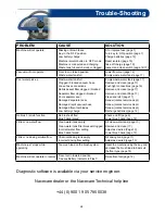
*   Bars cycle up and down  

continuously  (from 1 to 10 and 10 

back to 1) and repeats.

* Accelerator pedal movement 

detected during V

ario start up se

-

quence (partially pressed or jammed).

* Foot or object on pedal during switch on or 

possible jamming of pedal.

* Machine will not operate.

* Remove object and ensure pedal is not jammed 

or depressed during switch on of V

ario.

* Cycle Key switch to resume normal 

operation .

* Bars cycle from 1 to 10 

continuously and repeats.

* Machine inhibit.

* Controller/harness incorrectly wired.

* Machine will not operate.

* Check controller and harness wiring with special 

attention to wires p2/03 and p2/10.

Correct 

wiring.  


*  Cycle Key switch to resume normal operation

* No indication on display

.

* Horn and beacon failure.

* Replace 20 

Amp fuse (If this doesn’t fix fault replace horn or beacon)

* No indication on display

.

* Brush motors continuously either of

or on while in transport mode.

* Microswitch failure.

* Brushes will not operate correctly

.

* Check wiring and microswitch on underside of 

machine by brushes ensuring microswitch is clear 

of debris.

* Replace/clean damaged components.

* No indication on display

.

* V

AC motor continuously either of

or on.

* Microswitch failure.

* V

acuum will not operate correctly

.

* Check wiring and microswitchs behind floor tool 

handle.

* Replace/clean damaged components.

Contact Service Agent.

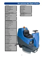
Summary of Contents for TTV 678-300T

Page 1: ...Owner Instructions Original Instructions Warning Read instructions before using the machine TTV 678 300T Ride on Scrubber Dryer Operator Instruction Manual ...

Page 2: ... tank warning light Brush pressure load adjustment Emergency stop button and horn Machine usage advice Breakaway floor tool feature Off aisle cleaning kit optional Machine Cleaning Tanks and Filters Floor tool Machine Charging Motor brake disengage lever Towing Free wheel function Battery care Trip sequences Trouble shooting recommended spare parts Warranty Wiring Diagrams Specifications Declarati...

Page 3: ...ool raise lower lever 10 Seat adjustment lever 11 Separator release catches 12 40 Amp battery fuses x3 13 Gel batteries 606167 14 Chemical dosing tank 5 litre 15 Accelerator pedal 16 Clean water tank emptying hose 17 Semi parabolic floor tool 18 Vacuum hose 19 Waste water emptying hose 20 Floor tool vacuum hose 21 Air separator assembly 22 Pedestrian warning light Machine Overview 1 3 4 5 6 7 8 9 ...

Page 4: ...6 1 Battery charge level indicator 2 Brush pressure Load indicator 3 Clean speed button 4 5 6 Operator pre set buttons 7 Water flow rate indicator 8 Brush speed indicator 9 Chemical mix indicator 10 Waste water Full indicator 11 Off aisle vacuum button 12 Main control On Off key 13 Emergency stop button 14 Forward Reverse switch 15 Horn 16 Charger status light ...

Page 5: ...se must be separated collected and sent for recovery in an environmentally friendly manner Caution Floorsign NOTE A risk assessment should be conducted to determine which PPE should be worn Ear Protection Safety Footwear Safety Hat Safety Gloves Face Mask Eye Protection Protective Clothing Hi Viz Jacket Rating label Personal Protective Equipment Recycling 1 2 3 4 5 6 7 8 Rating Label Company Name ...

Page 6: ... appliance or those specified in the instruction manual The use of other brushes may impair safety A full range of brushes and accessories are available for this product Only use brushes or pads which are suitable for the correct operation of the machine for the specific task being performed It is essential that this equipment is correctly assembled and operated in accordance with current safety r...

Page 7: ...tery fuse holders as illustrated Fig 2 Remove transit block from pallet fig 2a 3 Insert key Fig 3 into ignition and turn quarter turn clockwise to the On position Ensure that the forward reverse switch is set to forward Fig 4 Depress accelerator pedal with right foot and slowly drive machine off of the pallet using the ramp provided Fig 5 Note The seat is fitted with a pressure sensor that disable...

Page 8: ...ically the side skirts should be examined and checked for wear and damage Replace as shown above Fig 6a Fig 6b Machine Set Up Fitting the side pod skirts Fitting the floor tool Lower the floor tool arm by moving the release lever to the upper position Fig 7 Push floor tool onto the holder and secure with the easy fit securing pin Fig 8 Push waste collection pipe onto the floor tool ensure a tight ...

Page 9: ...lose side pod and while keeping the side pod pushed in set to appropriate width see setting the width Fig 12 Safety gloves are recommended for the changing of used brushes Owning the TTV 678 ride on scrubber dryer is like having 3 machines in one With three width settings the operator can quickly adapt the machine to any cleaning situation without the need for any tools The machine can be set to c...

Page 10: ...To fill the clean water tank lift the cover flap Fig 14 to expose the filler cap Unscrew the filler cap Fig 15 and fill the tank using a hose Fig 16 or preferred method Note Great care must be taken to ensure that contaminants leaves hair dirt etc are not allowed to enter the clean water tank during the filling process If using a bucket or similar ensure it is always clean and free from debris Fil...

Page 11: ...scrubber dryer has an optional automatic chemical dosing system Simply fill the 5 litre chemical dosing bottle and the machine will deliver the correct mix ratio as set by the operator depending on the floor and cleaning conditions To fill the chemical dosing bottle first lift up the waste water tank Fig 18 remove the dosing bottle unscrew the bottle cap Fig 19 and fill with appropriate cleaning c...

Page 12: ...oot pedal see Fig 20 press down the release lever see Fig 21 and gently release the foot pedal to lower the brush deck see Fig 22 Note If the brush width has not been set see Setting the width adjustment on page 8 before proceeding Lower the floor tool by moving the release lever to the upper position Fig 23 NOTE The machine will not reverse while the floor tool is in the lowered position Causes t...

Page 13: ...d as required depending on floor type and level of soiling Set Water Flow Rate as required depending on floor type and level of soiling 0 2 5 g p m 0 5 g p m 0 7 5 g p m 1 0 g p m Sitting in the driving position adjust the seat forwards or backwards as necessary by using the lever found on the left hand side see Fig 24 Note The seat is fitted with a pressure sensor that disables the machine until ...

Page 14: ...ill operate at up to a maximum speed of 7 0km hr When the waste water tank becomes full a red warning light will illuminate on the operator control panel as illustrated and the vacuum motor will stop automatically after 5 seconds The waste water tank requires emptying see page 17 The machine is equipped with a brush pressure load warning system If the brush load increases due to changing floor typ...

Page 15: ...D NOTE Care must be taken to reduce speed when cornering or when manoeuvring around obstacles To operate select forward or reverse press the accelerator pedal Vacuum pick up water flow and chemical dose will turn on automatically and the machine will move forward The clean water chemical mix is dispersed evenly via THRU FEED scrubbing brushes The waste water is then retrieved by the suction floor ...

Page 16: ...t See Fig 30 The optional off aisle cleaning kit gives added flexibility to the operator The kit can be used to clean hard to reach inaccessible areas Press the blue auxiliary switch on the dashboard see Fig 31 ensure the floor tool is in the lowered position see Fig 31a so only the vacuum will operate and all other functions on the machine will become disabled If floor tool is in the raised posit...

Page 17: ...machine Remove debris basket filter and rinse using clean water and refit IMPORTANT If the debris basket is allowed to become clogged vacuum performance can deteriorate Machine Cleaning Located in your waste water top tank is a full tank switch this stops your machine from working once the waste water reaches its maximum limit Sometimes the switch gets clogged and blocked clean to ensure correct o...

Page 18: ...e Rinse the floor tool assembly with clean water and refit Periodically the floor tool blades should be examined and checked for wear and damage The blade removal is easy Simply start by removing the four retaining pins see Fig 33 turn the floor tool over and separate the blade carrier from the body see Fig 34 Peel away the blades from their locating lugs see Fig 35 and examine or renew as require...

Page 19: ...or should drive the machine straight to a suitable charge point The large capacity gel batteries are sealed for life and are totally maintenance free The on board charger automatically monitors the charging process and will switch off when the batteries are fully charged The machine charging point is located under the top tank see Fig 37 Insert the charging lead required for your country see start...

Page 20: ...rted between the brake arm and drive housing see Fig 42 Once the key has been inserted see Fig 42 the motor brake will be fully disengaged The machine will now be in full free wheel mode When towing the machine ensure that a suitable tow bar is used Care must be taken when towing maximum speed to be no more than 7kmh The machine can be towed from the front bar as indicated see Fig 43 WARNING WHEN ...

Page 21: ...ur battery life please follow the simple steps below Under normal daily usage Recharge batteries after each use regardless of machine operation time see page 19 Recharge the machine fully after its last use Do not leave the machine in a discharged state Battery Care Under abnormal use i e leaving the machine without charging for a period of time we advise that you follow these steps If the machine...

Page 22: ...ce dam aged components 3 Bars Flash continuously Brush motor over current trip has occurred Rough floor surface Brush motor has failed or is damaged Brush motor bad connection Intermittent brush trip Brush Motor doesn t run or runs intermittently Brush type suitable for floor surface Cycle Key switch to resume normal operation If the above fails then Switch off machine Check brush motor for damage...

Page 23: ...ing and connections to pump Replace damaged components Cycle Key switch to resume normal operation 9 Bars flash 4 times with pause Detergent pump failure to operate Failure of pump or wiring short circuit No detergent supplied in water mix to cleaning head Check wiring and connections to pump Replace damaged components Cycle Key switch to resume normal operation 9 Bars flash 5 times with pause Sol...

Page 24: ...d floor tool blades Low battery charge Empty waste water tank page 17 Remove and clean page 17 Push tight connections page 16 Remove and clean page 17 Remove and clean Page 17 Clean and refit page 17 Renew contact service dept Renew contact service dept Renew contact service dept Recharge batteries page 19 No brush scrub function No brushes fitted Brush deck raised Check and fit page 9 Lower brush...

Page 25: ...t Filter 221047 40A Battery Fuses TTV 678 300T 208191 Vac Hose 208192 Suction Hose 208042 Gas Strut 229834 RH Side Buffer 229835 LH Side Buffer 303809 Chuck Assembly 206933 Forward Reverse Switch 208077 Bottom Tank Filler 206944 Top Tank Float Switch 206939 Rear Wheels 208048 Display Panel Membrane 205263 Brush Motor 208790 Bottom tank filter 208169 PG Controller 321406 Water Pump 321663 Dosing Pu...

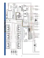
Page 26: ...26 WD 0359 A18 01 04 2014 ...
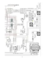
Page 27: ...27 ...

Page 28: ...km h 3 5km h 11 650mm 750mm 850mm Brush Speed Water Capacity Nuchem Capacity Water Flow rate Nuchem Mix Gross Weight Full Gross Weight Full Plus 75KG Operator Hand Arm Vibration Measurement Whole Body Vibration Measurement Dimensions 50 100 150 200 rpm 31 7 gallon 1 gallon 1 00 gpm 0 75 gpm 0 50 gpm 0 25 gpm 25 1 50 1 75 1 100 1 620Kg 695Kg 2 1m s2 BS EN ISO 5349 Uncertainty 1 0 525m s2 ISO 2631 1...

Page 29: ...29 Notes ...

Page 30: ...30 Notes ...

Page 31: ...31 Notes ...

Page 32: ...233890 11 14 A13 This machine has been packed with the following Charging Lead Fuses Isolator Key Pin Hose Hook 38 32 mm Adaptor Signed ...

Reviews: