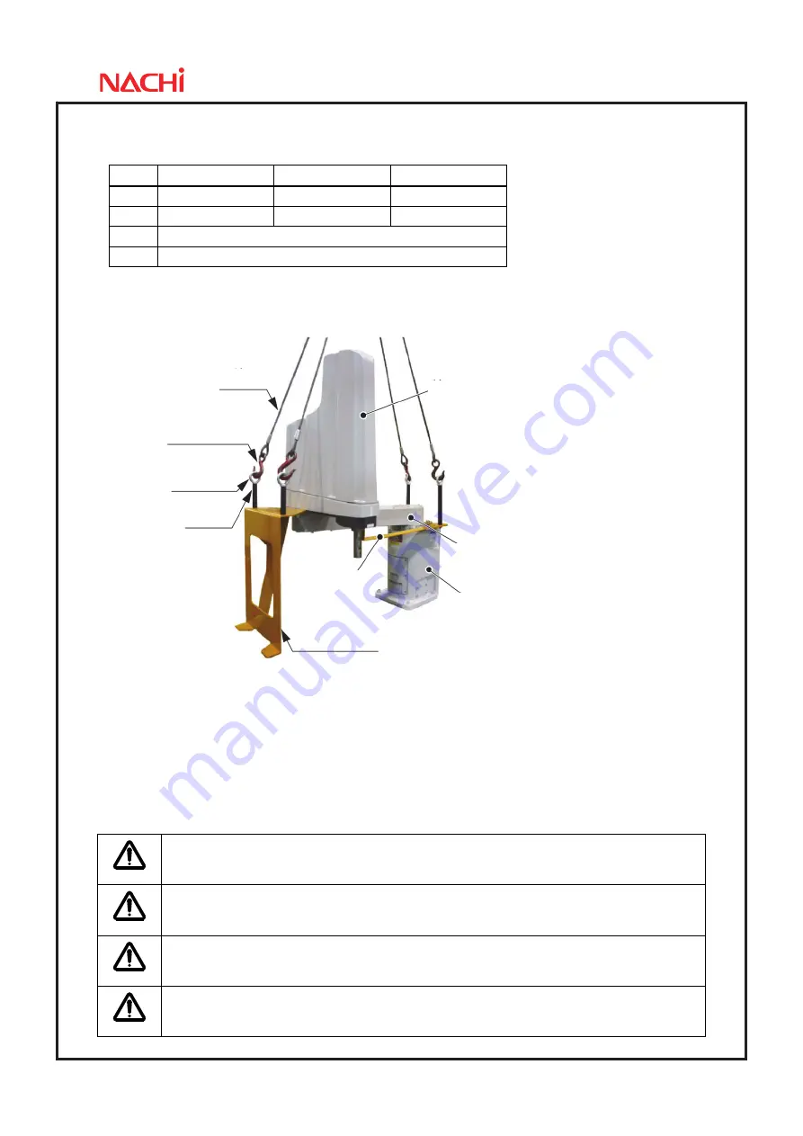
Page-23
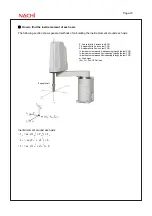
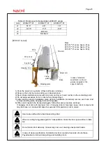
Table 9-1 Robot pose for transportation (ES06-01 series)
Axis ES06-35**-01 ES06-45**-01 ES06-55**-01
J1 57.5°
28°
19°
J2 -147.5°
-118°
-109°
J3 -49.6mm
J4 Not
fixed
【
ES12-01 series
】
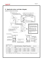
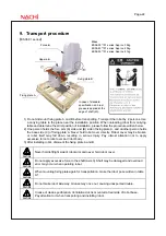
1) Hook the wires to 4 eye bolts. (Check all hooks certainly.)
2) Hang up the robot by crane and move to desired place.
3) Never make interference wires with robot arm and cover. Insert cushion in the contacting point.
4) Do not apply excessive force to robot when transporting it.
5) After locating robot to installation place (refer to installation procedure) remove wire hook. And
remove standing plate, hanging tool and fixing plate.
6) When robot needs to be transported again, follow the same procedure as above.
If hanging robot arm with improper tool or hanging robot of improper pose, robot components
may be broken or robot will fall down because its COG position is not in center.
CAUTION
Use 4 wires without fail when transporting robot.
CAUTION
When mounting fixing plate again for transportation, make the robot pose written in table
9-2.
CAUTION
Do not make robot side-way. Grease may ooze out, causing unexpected trouble.
CAUTION
In case of clean specification, Ventilation duct is mounted at rear side of robot base.
Pay attention to it when transporting and installing robot.
Mass
ES12-55**-01 series: Approx. 65kg
ES12-70**-01 series: Approx. 67kg
ES12-85**-01 series: Approx. 69kg
In case of standard
specification, anti-rust
grease is applied at the
edge of shaft (J3).
Fore arm
Upper arm
Fixing
plate
Standing plate
Base
Wire
Wire hook
Eye bolt
Hanging tool


