1.2 EtherNet/IP of this controller
1-3
1.2.2 Performance table
Table 1.2.1 Performance table
Item
Specification
Number of channels
Up to four installed channels
Scanners / adapters
Scanners and adaptors can be used.
Adaptors can be configured independently for each channel.
Communications
Supports I/O communication only
Number of I/O signals
Capable of using up to 2048 input signals (256 bytes) and up to 2048
output signals (256 bytes) for all channels combined, communication
can be covered by the general-purpose signals of this
controller.
(When using embedded PLC)
Addresses
The IP address, subnet mask, and default gateway of this controller
can be set for each channel by key entry from the teach pendant.
Transfer rate
10 Mbps, 100 Mbps
The transfer rate is set automatically.
Processing of input data when a
communication error occurs
You can select whether to maintain or clear input signal status when a
communication error occurs.
Possible causes of errors are given below.
・
Hardware error of the EtherNet/IP board
・
Broken cable or hub error
・
Incorrect node address setting
CAUTION
I/O status may not be normal if an error occurs and the LED indicating a problem lights.
Take great care as the interlock functions of the robot, jigs, and/or other devices may fail
to operate normally, resulting in unintended operation.
IMPORTANT
The following configuration tool (prepared by the user) is necessary to use the scanner
function.
・
RsNetworx for EtherNet/IP (from Rockwell)
1.2.3 Hardware configuration
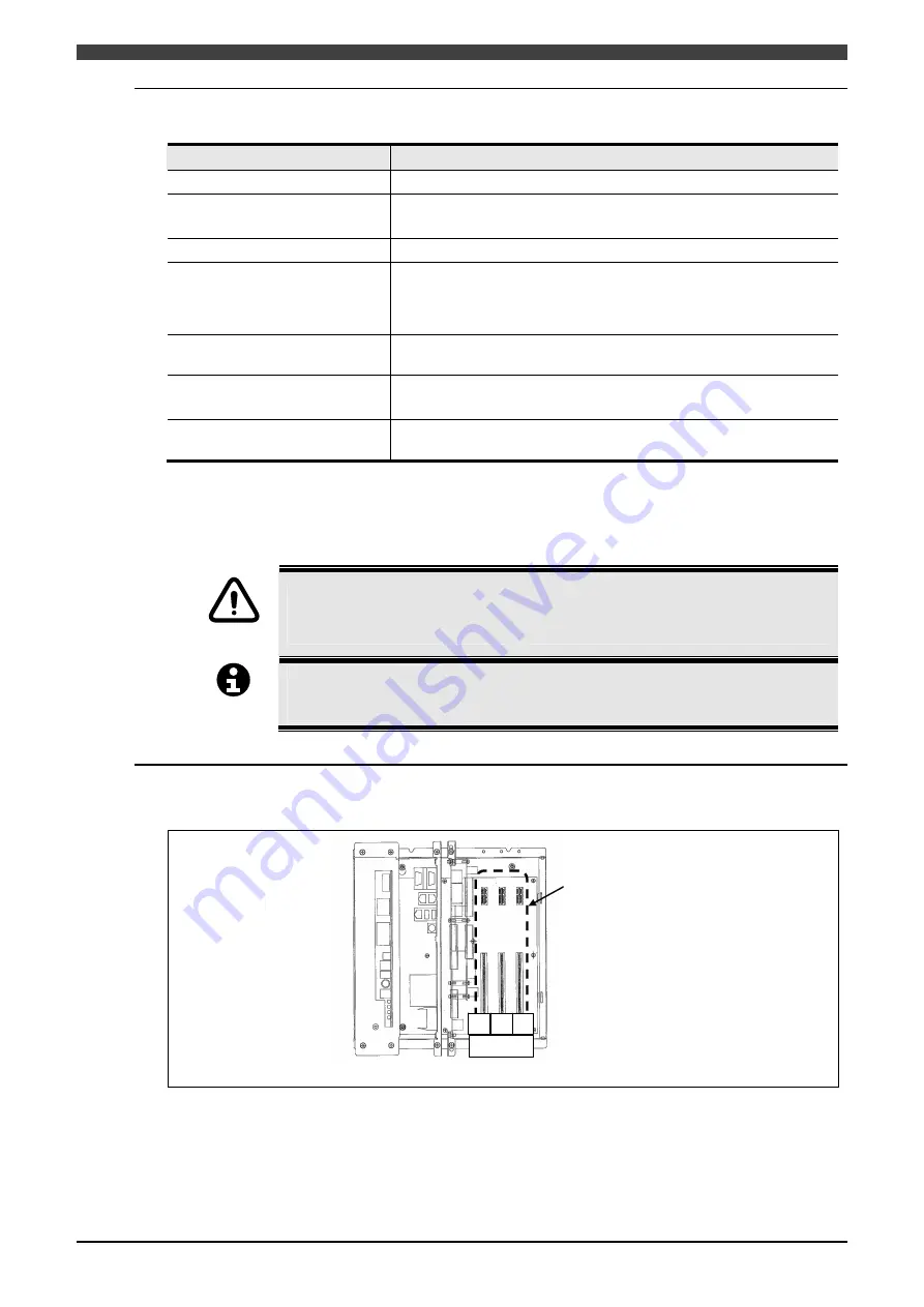
EtherNet/IP board should be mounted on one of three PCI slots in CPU unit.
Rack unit
Three PCI slots
#1 #2 #3
Slot ID
Fig. 1.2.2 PCI slots
Summary of Contents for FD
Page 2: ......
Page 4: ...Table of Contents 2 ...
Page 10: ...2 1 Needed Parts 2 2 NOTE ...
Page 47: ......


