1.1 Outline
1-3
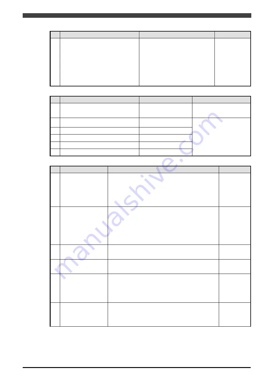
Safety performance
Item
Specifications
Remarks
1
Motor power control sequence.
Monitoring of position (operating range,
joint angle)
Monitoring of speed
Monitoring of stop
Monitoring of stop in area
Safety network(RM20-30 only)
EtherNet/IP Safety communication
Safety network(RMU20-40 only)
PROFINET Safety communication
Category 4
PL(Performance Level)=e
MTTFd = 75.15
DC = 94.34
CCF = 75
SIL3
PFD = 4.35e
-4
PFH = 1.99e
-8
proof test interval 5years
Response time of safety signals
Item
Specifications
Remarks
1
Motor power control sequence
Less than 30msec.
(Except the one that can
be set by parameter )
The time from inputting of the
safety input to shutting off of
the safety output
2
Monitoring of position (operating range,
joint angle)
Less than 50msec.
3
Monitoring of speed
Less than 70msec.
4
Monitoring of stop
Less than 50msec.
5
Monitoring of stop in area
Less than 50msec.
6
Safety network
Less than 50msec
The time from the error
occurrence to shutting off of
the safety output
Monitoring of operating range
Item
Specifications
Remarks
1
Restricted range 1
Safety fence
The outside of the straight line randomly defined from the
center of the robot is a restricted area.
Up to 8 straight restricted lines can be defined.
Up to 4 sets can
be set
It is possible to
switch using the
selection
signal from
safety network.
2
Restricted range 2
Partial range
The partial inside of the area enclosed by straight lines
within the restricted range is defined as a restricted area.
A restricted range can be defined using a maximum of 4
straight lines, and up to 8 locations can be specified.
A three-line triangle or a four-line rectangle can be
specified. For the z direction, the upper and lower limits
can be specified in the world coordinate system.
This function will enabled by general-purpose safety input.
3
Restricted object 1
Restriction on tool
spheres
Specify 20 spheres or cubes for each tool. If the restricted
range is exceeded, set to the condition conforming to the
method of restriction.
4
Restricted object 2
Arm restriction
Specify 10 spheres or cylinders on the robot arm. If the
restricted range is exceeded, set to the condition
conforming to the method of restriction.
5 Tool
Up to 32 tools are supported.
Monitors by the tool number from the robot controller.
Monitor input 4 ch
16 tools are
available
For more, please
use the safety
network function.
6 Restricted
coordination
The world coordinates system in the JIS coordinate is
used for operating range monitoring.
Therefore, for a robot placed on a stand or wall-mounted
robot, specify using “constant: format and initial setting:
installation position”.
Summary of Contents for RMU20-20
Page 2: ......
Page 6: ...Contents 4 ...
Page 8: ......
Page 26: ...1 4 EC DECLARATION OF CONFORMITY FOR MACHINERY 1 18 NOTE ...
Page 68: ...2 9 Enabling RMU 2 40 NOTE ...
Page 70: ......
Page 100: ...3 4 Setting when a slider unit is used 3 30 NOTE ...
Page 102: ......
Page 138: ...4 4Approval 4 36 8 Approval is completed The following screen will be displayed ...
Page 144: ......
Page 154: ...5 4Trouble shooting 5 10 NOTE ...
Page 156: ......
Page 166: ...6 4Trouble shooting 6 10 NOTE ...
Page 168: ......
Page 189: ......


