4.2Setting of parameters
4-12
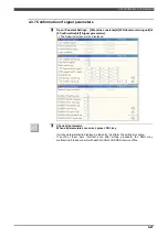
4.2.6 Setting the logical operation parameters
1
Open <Constants> - [3 machine constants]
–
[34 Robot monitoring unit]
–
[1
Setting]
–
[8 Logic parameters].
>> The following screen will be displayed.
Operator class
SPECIALIST
is necessary to change these parameters.
2
Select the logic operation relay and to be set and then set the logic parameters.
The above setting example is as follows;
General safety output 1 = Internal relay (Teach mode)
AND
Internal relay (Inside Part#2)
OR Inside safe stop
General safety output 2 = Safety input relay (Robot E.STOP)
General safety output 3 = Safety input relay (Robot E.STOP)
IMPORTANT
If the RMU was replaced, press the "Complete" key even if there are no changed
parameters.
General safety output 1
General safety output 2
General safety output 3
Blank or NOT
can be
selected.
Group can be selected.
Safety in.relay
Safety out.relay
Internal relay
Item can be
selected
AND or OR can be
set.
Summary of Contents for RMU20-20
Page 2: ......
Page 6: ...Contents 4 ...
Page 8: ......
Page 26: ...1 4 EC DECLARATION OF CONFORMITY FOR MACHINERY 1 18 NOTE ...
Page 68: ...2 9 Enabling RMU 2 40 NOTE ...
Page 70: ......
Page 100: ...3 4 Setting when a slider unit is used 3 30 NOTE ...
Page 102: ......
Page 138: ...4 4Approval 4 36 8 Approval is completed The following screen will be displayed ...
Page 144: ......
Page 154: ...5 4Trouble shooting 5 10 NOTE ...
Page 156: ......
Page 166: ...6 4Trouble shooting 6 10 NOTE ...
Page 168: ......
Page 189: ......


