4.2Setting of parameters
4-14
4.2.7 Setting the Safety network parameters (RMU20-30)
This screen is displayed only for RMU20-30.
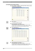
1
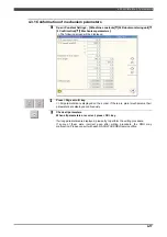
Open <Constant Setting> - [3 Machine constants]
–
[34 Robot monitoring
unit]
–
[1 Setting]
–
[9 Safety network parameters].
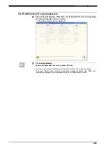
>> The following screen will be displayed.
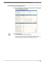
2
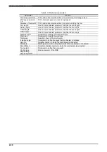
Set the required parameters with reference to the Table 4-8.
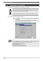
If there is no parameter to be updated, following operation is necessary.
IMPORTANT
If the RMU was replaced, press the "Complete" key even if there are no changed
parameters.
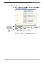
3
After setting, press f12 <Complete>.
>> When setting is done correctly, following message is displayed. But this is
normal. After closing this message with [R] key, perform the confirmation
operation.
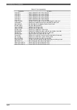
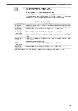
Table 4-8 Setting items for the safety network parameters
Parameter
Description
Default
Safety
inputs/outputs
This is a Disable/Disable switch for the safety network function.
To use this function, select "Enabled".
Disabled
IP Address
This is the IP address that is used for the EtherNet/IP Safety.
0.0.0.0
Subnet mask
This is the Subnet mask that is used for the EtherNet/IP Safety.
0.0.0.0
Default gateway
This is the Default gateway that is used for the EtherNet/IP Safety.
0.0.0.0
Input bytes
Set the input size of the I/O in bytes.
0
Output bytes
Set the output size of the I/O in bytes.
0
Operator class
SPECIALIST
is necessary to change these parameters.
Summary of Contents for RMU20-20
Page 2: ......
Page 6: ...Contents 4 ...
Page 8: ......
Page 26: ...1 4 EC DECLARATION OF CONFORMITY FOR MACHINERY 1 18 NOTE ...
Page 68: ...2 9 Enabling RMU 2 40 NOTE ...
Page 70: ......
Page 100: ...3 4 Setting when a slider unit is used 3 30 NOTE ...
Page 102: ......
Page 138: ...4 4Approval 4 36 8 Approval is completed The following screen will be displayed ...
Page 144: ......
Page 154: ...5 4Trouble shooting 5 10 NOTE ...
Page 156: ......
Page 166: ...6 4Trouble shooting 6 10 NOTE ...
Page 168: ......
Page 189: ......


