4.3Confirmation of parameters
4-23
5
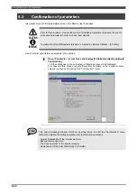
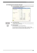
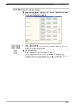
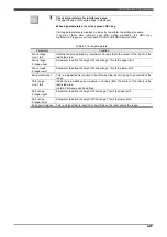
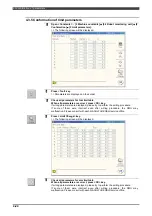
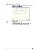
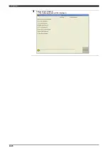
Check all parameters for interference area.
Change the page until desired page is displayed.
When all parameters are correct, press <OK> key.
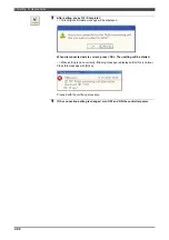
If wrong parameters are displayed, please try to perform the writing procedure.
If some of them were incorrect even after writing procedure, the RMU may
malfunction. Please consult with each NACHI-FUJIKOSHI service office.
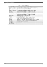
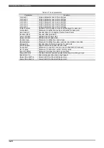
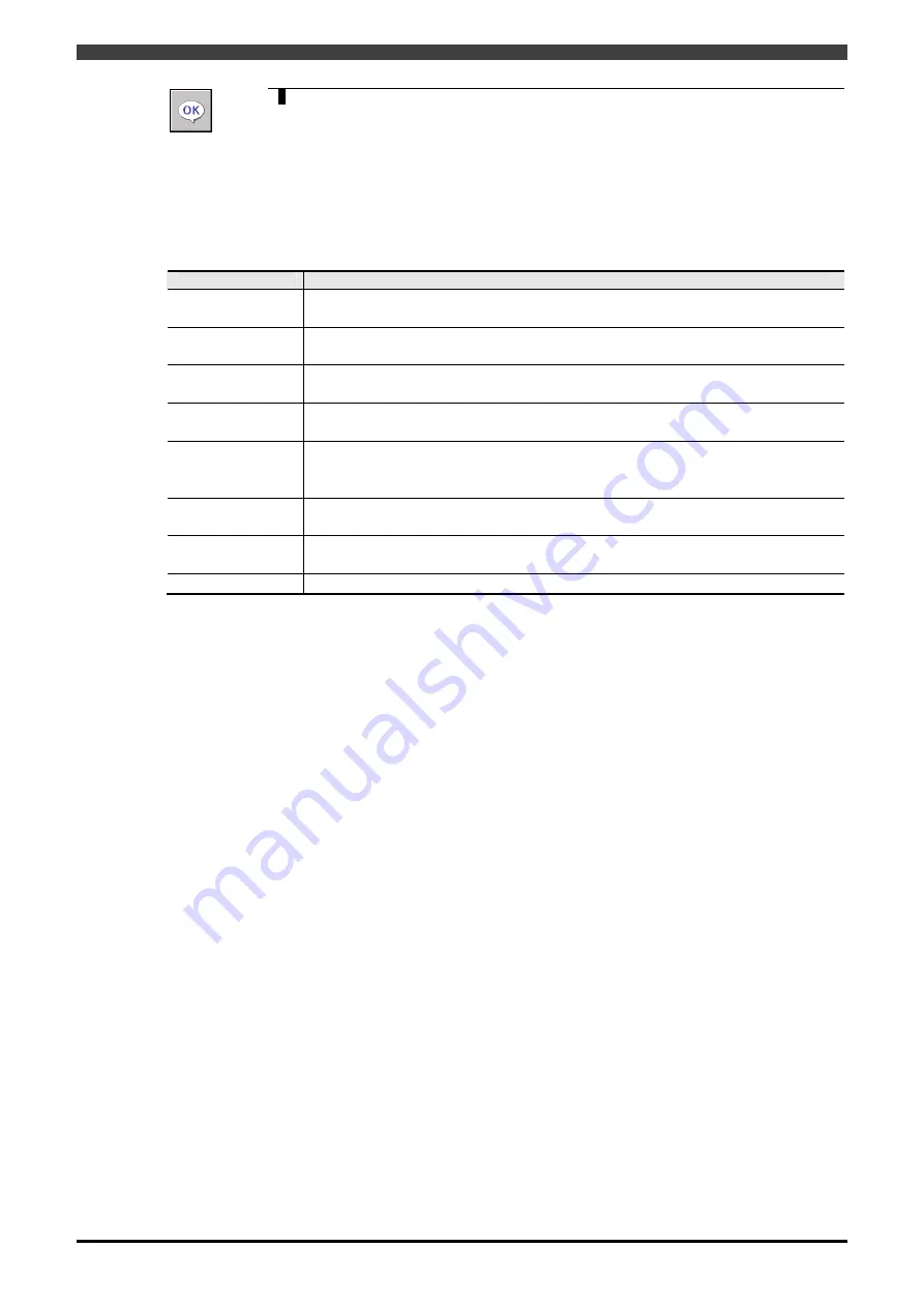
Table 4-13 Area parameters
Parameter
Function
Fence range
Line 1 to 8
Outside the area defined by maximum of 8 lines (from the center of the robot) is the
restricted area.
Fence range
Z range upper
Parameter to define the height of Fence range. This is the upper limit.
Fence range
Z range lower
Parameter to define the height of Fence range. This is the lower limit.
Exit permit signal
This is a signal that is required to be ON when the robot is trying to go outside of the
range
Part. range
Line 1 to 4
Inside the area defined by maximum of 4 lines (from the center of the robot) is the
restricted area.
Up to 8 Part.range can be defined.
Part. range
Z range upper
Parameter to define the height of Part.range. This is the upper limit.
Part. range
Z range lower
Parameter to define the height of Part.range. This is the lower limit.
Entry permit signal
This is a signal that is required to be ON when the robot enters the range
Summary of Contents for RMU20-20
Page 2: ......
Page 6: ...Contents 4 ...
Page 8: ......
Page 26: ...1 4 EC DECLARATION OF CONFORMITY FOR MACHINERY 1 18 NOTE ...
Page 68: ...2 9 Enabling RMU 2 40 NOTE ...
Page 70: ......
Page 100: ...3 4 Setting when a slider unit is used 3 30 NOTE ...
Page 102: ......
Page 138: ...4 4Approval 4 36 8 Approval is completed The following screen will be displayed ...
Page 144: ......
Page 154: ...5 4Trouble shooting 5 10 NOTE ...
Page 156: ......
Page 166: ...6 4Trouble shooting 6 10 NOTE ...
Page 168: ......
Page 189: ......


