background image

5.4Trouble shooting 

5-10


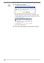
NOTE 


Summary of Contents for RMU20-20

Page 1: ...those individuals who have attended one of our robot course When using this robot observe the low related with industrial robot and with safety issues in each country This operating manual must be given without fail to the individual who will be actually operating the robot Please direct any queries about parts of this operating manual which may not be completely clear or any inquiries concerning ...

Page 2: ......

Page 3: ...2 15 2 3 3 Safety outputs 2 18 2 3 4 Back check circuit 2 19 2 3 5 Monitor inputs 2 20 2 3 6 Monitor outputs 2 21 2 3 7 Motion controller interface 2 22 2 3 8 Encoder interface 2 22 2 3 9 Motor interface 2 22 2 3 10 Power supply 2 22 2 4 Precautions when Installing RMU inside the Controller 2 23 2 4 1 Low Voltage Directive requirements to be satisfied compliance with EN50178 2 23 2 4 2 EMC Directi...

Page 4: ...Example2 3 29 Chapter 4 Monitoring Unit Settings 4 1 Configuration flow of setting procedure 4 1 4 2 Setting of parameters 4 4 4 2 1 Setting of mechanism parameters 4 5 4 2 2 Setting of axis parameters 4 6 4 2 3 Tool parameters 4 8 4 2 4 Setting of stop parameters 4 9 4 2 5 Setting of signal parameters 4 10 4 2 6 Setting the logical operation parameters 4 12 4 2 7 Setting the Safety network parame...

Page 5: ...g 5 9 5 4 1 Trouble shooting via the LEDs 5 9 5 4 2 Error codes 5 9 Chapter 6 PROFINET Safety network function 6 1 Outline of the PROFINET safety network function 6 1 6 2 Setting for PROFINET module 6 2 6 2 1 Fieldbus settings 6 2 6 2 2 Setting for the PROFINET Safety 6 4 6 3 Safety network parameters 6 6 6 3 1 Assignment of the network I O signals 6 6 6 4 Trouble shooting 6 8 6 4 1 Trouble shooti...

Page 6: ...Contents 4 ...

Page 7: ...ng unit 1 1 1 1 3 Specifications 1 2 1 1 4 Type and serial number 1 8 1 2 Risk Assessment 1 9 1 3 Connection 1 10 1 3 1 Required parts and installation FD controller 1 10 1 3 2 Required parts and installation CFD controller 1 10 1 3 3 Sequence board UM367 20 1 11 1 3 4 Connection of safety inputs 1 12 1 3 5 Connection of safety outputs 1 16 1 4 EC DECLARATION OF CONFORMITY FOR MACHINERY 1 17 ...

Page 8: ......

Page 9: ...ngle monitoring function This function monitors the operating ranges of the robot axes and it shuts off the safety outputs and stops the robot safely when movement along any one of the axes is about to exceed an operating range which has been set Speed monitoring function This function shuts off the safety outputs and stops the robot safely when the TCP speed exceeds 250 mm sec in TEACH mode Also ...

Page 10: ...points Redundant safety output with back check 5 Monitor input signals All 16 ports 6 Monitor output signals All 9 ports 7 Number of axes to be monitored Max 8 axes 8 Position detector Serial encoder Panasonic N400 format Nikon A format also bus communication type Magnetic pole position detection circuit of the motor 9 Parameter transfer Transferred from the robot controller 10 Communication of th...

Page 11: ...d lines can be defined Up to 4 sets can be set It is possible to switch using the selection signal from safety network 2 Restricted range 2 Partial range The partial inside of the area enclosed by straight lines within the restricted range is defined as a restricted area A restricted range can be defined using a maximum of 4 straight lines and up to 8 locations can be specified A three line triang...

Page 12: ...2 Method of restriction If the restricted object exceeds the restricted range perform operation as follows TEACH mode Safety output OFF Stop Category 0 PLAYBACK mode Safety output OFF Stop Category 0 Errors can be cleared by pressing LSSW button LS releasing button Monitoring of speed Item Specifications Remarks 1 Basic functions TEACH mode Monitor the linear speed of TCP does not exceed the 250mm...

Page 13: ...when the tool number is unmatch and the tool center point moves too far from the setting value Monitor input 4 ch 16 tools are available For more please use the safety network function 2 Parameter setting If the restricted object exceeds the restricted range perform operation as follows TEACH mode Safety output OFF Stop Category 0 PLAYBACK mode Safety output OFF Stop Category 0 Errors can be clear...

Page 14: ...output signal Motor power control sequence processing Item Specifications Remarks 1 Safety inputs This is to read the safety signal For further details see 2 3 2 Safety inputs Diagnoses system short circuit between inputs input circuit failure disparity between two inputs and over current If an error is detected safety output is turned OFF 2 Safety outputs This is to output the safety signal For f...

Page 15: ...ion may be temporarily caused by the build up of dust and dirt approximate environments inside a control panel equivalent to IP54 in the control rooms or on the floors of average factories Applicable directive Directive Description Machinery directive EN ISO 13849 1 2008 EN ISO 10218 1 2011 IEC 62061 2005 EN 60204 1 A1 2009 Safety of machinery Manipulating industrial robots Safety Safety of machin...

Page 16: ... Outline 1 8 1 1 4 Type and serial number Model and serial number of the robot monitoring unit can be checked on the nameplate that is attached to the monitoring unit Type RMU20 20 or RMU20 30 or RMU20 40 ...

Page 17: ... integrity level SIL SIL is stipulated in the IEC 61508 standard In this method of assessing risks consideration is given to the extent of the effects of the danger events the frequency of the exposure to them the possibility of avoiding them and their probability with which they occur and the frequency of parts failures is categorized into the four levels of 1 to 4 The target failure frequency is...

Page 18: ...detection function ROX T or ROX CT 1 3 2 Required parts and installation CFD controller Table 1 2 Optional products for RMU of CFD controller Product name Model number RMU unit CFD OP145 A UM367 20 is included In case of CFD controller RMU needs separated box Customer needs to install sequence board in robot controller and needs to connect RMU with robot controller Please refer to CFD controller T...

Page 19: ... drive unit Connected to the IPM drive unit CNLINE Process control panel Connected to the terminal block TBX 1 CNARC Not used CNP24V 24V power Connected to the raiser board Jumper settings On this board 3 jumper switches JP1 2 and 3 are equipped To separate the emergency stop circuits from robot controller and connect it to the power source of external devices like process controller change the se...

Page 20: ... shown in the Fig 1 2 Bear in mind that the signals cannot be connected in ways such as the one shown in Fig 1 3 Example In case of robot emergency stop inputs Fig 1 3 Connection diagram of safety input signals Fig 1 4 Example of how the safety input signals cannot be connected Connection of monitor input Electrical specification Rating DC26V 5mA Connect the dry contacts To prevent defective conta...

Page 21: ...afety input 11 17 IN9A SI General safety input 11 18 IN9B SI General safety input 12 19 IN9B SI General safety input 12 20 IN10A SI General safety input 21 21 IN10A SI General safety input 21 22 IN10B SI General safety input 22 23 IN10B SI General safety input 22 24 IN11A SI General safety input 31 25 IN11A SI General safety input 31 26 IN11B SI General safety input 32 27 IN11B SI General safety i...

Page 22: ...1 B11 22 IN10A SI General safety input 21 A12 23 IN10B SI General safety input 22 B12 24 IN10B SI General safety input 22 A13 25 IN11A SI General safety input 31 B13 26 IN11A SI General safety input 31 A14 27 IN11B SI General safety input 32 B14 28 IN11B SI General safety input 32 A15 29 IN12A SI General safety input 41 B15 30 IN12A SI General safety input 41 A16 31 IN12B SI General safety input 4...

Page 23: ... to the following descriptions Single wire φ1 6 mm Twisted wire Flexible wire φ1 25mm2 When connecting the wire as it is the pealed length of the wire should be 11mm Concerning the connection it is strongly recommended to use blade shape terminal with a plastic insulator for the wire to prevent the electric short circuit with the peripheral devices In a case like that please select a terminal whos...

Page 24: ...check 2 A7 OUT4A SO General safety output 31 B7 OUT4A SO General safety output 31 A8 OUT4B SO General safety output 32 B8 OUT4B SO General safety output 32 A9 BK4 BI Back check 3 B9 BK4 BI Back check 3 A10 B10 SO Safety outputs BI Back check inputs Cable side applicable receptacle housing Tyco electronics type 2 1318118 9 20pins Y type Cable side connection terminal Tyco electronics type 1318108 1...

Page 25: ...nt safety requirements Part 1 Robot EN 60204 1 2006 Safety of machinery Electrical equipment of machines Part 1 General requirements EN 55011 2007 Industrial scientific and medical ISM radio frequency equipment Electro magnetic disturbance characteristics Limits and methods of measurement EN 61000 6 2 2005 Electromagnetic compatibility EMC Part 6 2 Generic standards Immunity for industrial environ...

Page 26: ...1 4 EC DECLARATION OF CONFORMITY FOR MACHINERY 1 18 NOTE ...

Page 27: ...ower supply 2 22 2 4 Precautions when Installing RMU inside the Controller 2 23 2 4 1 Low Voltage Directive requirements to be satisfied compliance with EN50178 2 23 2 4 2 EMC Directive requirements to be satisfied compliance with EN61326 3 1 2 23 2 4 3 Other processing the cables connected to RMU20 2 24 2 5 Operating Range Angle and Speed Monitoring Function 2 25 2 5 1 Collaborative operation wit...

Page 28: ...2 7 Logical operation output function 2 35 2 8 RMU error signal output Application signals 2 37 2 9 Enabling RMU 2 38 ...

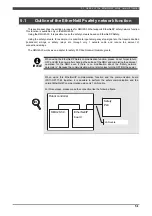
Page 29: ...ions for a system in which two robots are operated by one teach pendant but it is just an example in reality there are many and varied systems and the safety measures required are also different Fig 2 1 Example of connections with external equipment 非常停止スイッチ 教示 再生切替スイッチ 等 Emergency stop Teach Auto switch 非常停止 安全停止 保護停止 Emergency stop Safety stop Protection stop 非常停止スイッチ イネーブルスイッチ Emergency stop En...

Page 30: ...erform speed and position monitoring it is used to set and check the parameters required with the monitoring unit transfer the information to from the RMU with the respective communications and output the information to the teach pendant and other equipment Robot Monitoring Unit RMU The RMU shuts off the drive power of the robot when trouble is deemed to have occurred as a result of monitoring the...

Page 31: ...2 2 Description of Exterior and Parts 2 3 2 2 Description of Exterior and Parts 2 2 1 View of exterior Fig 2 2 Front view of RMU20 20 Fig 2 3 Side view of robot monitoring RMU20 20 ...

Page 32: ...2 2 Description of Exterior and Parts 2 4 Fig 2 2 Front view of RMU20 30 RMU20 40 Fig 2 3 Side view of robot monitoring RMU20 30 RMU20 40 ...

Page 33: ...status of input output signals Table 2 1 Status of status display LED Classification Name Description 1 Power on Software version of the RMU is displayed 2 During normal operation During normal operation the display is as follows Ex In case of software version V1 1 最初へ戻る Back to the beginning ...

Page 34: ...2 2 Description of Exterior and Parts 2 6 3 When an error occurs Error number is displayed EX In case of Error code 01 Assist code 2345H 最初へ戻る Back to the beginning ...

Page 35: ...PIN2 I PLAYBACK mode A10 GPIN3 I TEACH mode B10 GPIN4 I Power shut off command A11 GPIN5 I System OK B11 GPIN6 I Not used A12 GPIN7 I LS release switch B12 GPIN8 I Gun axis brake release A13 P1 PO DC24V B13 P1 PO DC24V A14 OUT1A SO Robot power ON 1 B14 OUT1A SO Robot power ON 1 A15 OUT1B SO Robot power ON 2 B15 OUT1B SO Robot power ON 2 A16 BK1 BI Robot power ON back check 1 B16 BK1 BI Robot power...

Page 36: ...al B4 S4 IO Encoder 4 Differential signal A5 S5 IO Encoder 5 Differential signal B5 S5 IO Encoder 5 Differential signal A6 S6 IO Encoder 6 Differential signal B6 S6 IO Encoder 6 Differential signal A7 S7 IO Encoder 7 Differential signal B7 S7 IO Encoder 7 Differential signal A8 S8 IO Encoder 8 Differential signal B8 S8 IO Encoder 8 Differential signal A9 IN4A SI Robot LS detection 1 B9 IN4A SI Rob...

Page 37: ...otor W phase B10 L5 I J5 motor L phase A11 U6 I J6 motor U phase B11 V6 I J6 motor V phase A12 W6 I J6 motor W phase B12 L6 I J6 motor L phase A13 U7 I J7 motor U phase B13 V7 I J7 motor V phase A14 W7 I J7 motor W phase B14 L7 I J7 motor L phase A15 U8 I J8 motor U phase B15 V8 I J8 motor V phase A16 W8 I J8 motor W phase B16 L8 I J8 motor L phase A17 U24A PO DC24V B17 U0A GO DC24V GND Receptacle...

Page 38: ... IO serial signal 7 CNGP2 Table 2 7 Connector CNGP2 pin allocation Pin no Circuit code I O Signal name Pin no Circuit code I O Signal name A1 OUT2A SO General safety output 11 B1 OUT2A SO General safety output 11 A2 OUT2B SO General safety output 12 B2 OUT2B SO General safety output 12 A3 BK2 BI Back check 1 B3 BK2 BI Back check 1 A4 OUT3A SO General safety output 21 B4 OUT3A SO General safety out...

Page 39: ...r area select signal stop monitoring signal or playback speed monitoring select signal 9 CNGP4 RMU20 20 Table 2 9 Connector CNGP4 pin allocation Pin no Circuit code I O Signal name Pin no Circuit code I O Signal name A1 IN7A SI Protective stop 1 B1 IN7A SI Protective stop 1 A2 IN7B SI Protective stop 2 B2 IN7B SI Protective stop 2 A3 IN8A SI External enable 1 B3 IN8A SI External enable 1 A4 IN8B S...

Page 40: ... stop 2 A7 IN8A SI External enable 1 B7 IN8A SI External enable 1 A8 IN8B SI External enable 2 B8 IN8B SI External enable 2 Receptacle housing at cable side JST Mfg No J21DF 16V KY 16 contacts Y type SI safety input 11 CN3 RMU20 30 RMU20 40 Table 2 11 Connector CN3 Pin no Circuit code I O Signal name Pin no Circuit code I O Signal name A1 GPOUT7 O Servo ON B1 OUTCOM O Output common A2 GPIN11 I Not...

Page 41: ...input 31 Note B5 IN11A SI General input 31 Note A6 IN11B SI General input 32 Note B6 IN11B SI General input 32 Note A7 IN12A SI General input 41 Note B7 IN12A SI General input 41 Note A8 IN12B IS General input 42 Note B8 IN12B SI General input 42 Note A9 IN13A SI General input 51 Note B9 IN13A SI General input 51 Note A10 IN13B SI General input 52 Note B10 IN13B SI General input 52 Note Receptacle...

Page 42: ...D4 SD5 SD6 SD7 SD8 GPO_2A GPO_2A GPO_2B GPO_2B GPO2_BC GPO2_BC GPO_3A GPO_3A GPO_3B GPO_3B GPO3_BC GPO3_BC N C XRDY_ON COM 24V COM GPI_1A GPI_1A GPI_1B GPI_1B CNGP1 GPI_2A GPI_2A GPI_2B GPI_2B GPI_3A GPI_3A GPI_3B GPI_3B GPI_4A GPI_4A GPI_4B GPI_4B GPI_5A GPI_5A GPI_5B GPI_5B GPOUT1 GPOUT2 GPOUT3 GPOUT4 GPOUT5 GPOUT6 GPOUT7 COM CNGP2 GPI_6A GPI_6A GPI_6B GPI_6B GPI_7A GPI_7A GPI_7B GPI_7B CNGP3 汎用...

Page 43: ...ction 2 Robot LS detection 2 IN4A IN4A IN4B IN4B Limit switch signal inputs installed in the robot in such a way that they are pushed when the robot axes move as far as their limits Limit switch signal for cutting off power to the motor Photo coupler input Rating DC26V Input current 5mA Over current protection provided Emergency stop 1 Emergency stop 1 Emergency stop 2 Emergency stop 2 IN5A IN5A I...

Page 44: ...rotection provided General input 41 General input 41 General input 42 General input 42 IN12A IN12A IN12B IN12B General purpose safety input signal Used for area select signal stop monitoring signal or playback speed monitoring select signal Photo coupler input Rating DC26V Input current 5mA Over current protection provided General input 51 General input 51 General input 52 General input 52 IN13A I...

Page 45: ...een the two inputs for a period in excess of 500 ms the Input signal diagnosis error unrecoverable error results the safety outputs are turned OFF and the unit s power must be turned off and turned back on Remove the cause of the error and then press Reset key twice from teach pendant When an input signal has changed from ON to OFF An error is identified if both signals of the two systems are not ...

Page 46: ...2 OUT4A OUT4A OUT4B OUT4B General safety output 3 An output operation based on the logical operation function can be used Connect the magnet switch or relay to each output circuit Also connect the b contact of magnet switch or safety relay in series to each back check input Refer to the case of the following connections Feedback circuit for detecting trouble in the output shutoff functions A circu...

Page 47: ...h b contact Signal for detecting the welding back check of the magnet switch Photo coupler input Rating DC26V Input current 5mA Over current protection provided General safety output 3 back check 3 back check 3 BK4 BK4 Signal from external safety relay and magnet switch b contact Signal for detecting the welding back check of the magnet switch Photo coupler input Rating DC26V Input current 5mA Ove...

Page 48: ...electing the mode in which the teaching operation via teach pendant is performed Connected to the selector SW on the operation panel Photo coupler input Rating DC26V Input current 5mA PLAYBACK mode GPIN2 This signal is for selecting the mode in which the playback operation is performed Connected to the selector SW on the operation panel Photo coupler input Rating DC26V Input current 5mA Tool numbe...

Page 49: ... off and on 2 3 6 Monitor outputs Electrical output specifications Photo MOS relay output DC30V 100mA Install a surge absorption circuit without fail when a coil circuit such as a relay is to be connected Table 2 17 Monitor outputs Signal name Circuit code Description Electrical specifications ES error GPOUT1 This signal is connected to the controller input This signal is turned OFF when monitorin...

Page 50: ...er interface Signal name Description S1 S8 S1 S8 The interface connects these signals for communicating with the encoder Communication specification RS485 two wires half duplex channel multi point serial communication Panasonic N400 format is supported Nikon A format is supported 2 3 9 Motor interface Signals are connected through this interface to the servo amplifier by the motor position detecti...

Page 51: ...nvironments inside a control panel equivalent to IP54 in the control rooms or on the floors of factories Power supply IMPORTANT The RMU20 is installed inside the robot controller for use The power supply with overvoltage category I must be used Category I denotes a power supply whose voltage has been reduced using a transformer by 3 or more stages from the power distribution grid Category III Cate...

Page 52: ... frequency electromagnetic field immunity Electrical fast transient burst immunity Surge Immunity Immunity to conducted disturbances induced by radio frequency fields Power frequency magnetic field immunity Voltage dips short interruptions and voltage variations immunity 2 4 3 Other processing the cables connected to RMU20 Ensure that a ferrite core with 2 or more turns is installed on the cable t...

Page 53: ...collaborative operation with human Robot is just one of constructive part in manufacturing system so robot is not designed enough safely for the collaborative operation with human Collaborative operation is dynamic so monitoring distance and monitoring speed should be determined by the risk assessment according to the system Displaying of speed and separating distance should be included in the inf...

Page 54: ...In addition by the status of selection signal which was assigned general purpose safety inputs 1 5 the robot will be able to enter partial restriction area The operation of the robot manipulator is restricted in such a way that protrusion beyond any of the operating ranges will be prevented by the virtual safety fence function of the robot controller Nevertheless it is still possible for the robot...

Page 55: ... to stop is described here If for some reason the robot has moved beyond an operating range which has been set before it stops it may be necessary to operate the robot and move it back inside the operating range In TEACH mode it is possible to turn motor power ON while pressing LS release SW inputting LS release SW signal POINT LS release SW signal cancels only the operating range and angle monito...

Page 56: ... is calculated as follows Estimating the overrun distancee Free running distance Braking distance TCP speed is calculated every 10msec Estimating the overrun distance is calculated from free running distance and braking distance Free running distance and braking distance is calculated from free running time and braking deceleration time which is set as parameter Safety output shut off Safety Area ...

Page 57: ...llowing menu Constant 3 Machine Constants 34 Robot Monitoring Unit 1 Settings 7 I O signal parameter Concerning the setting method refer to 4 2 4 I O signal parameter The error will occur if the TCP moving the distance which has been set by the parameter Distance of tool match after tool number mismatch was detected When this error is detected the safety output will be turned OFF and the robot wil...

Page 58: ...ol number Connect the signals from the tool to the Tool No 1 4 on the terminal block TBX 1 in the robot controller as follows P1 24V ツール番号1 ツール番号2 ツール番号3 ツール番号4 監視ユニット TBX 1 ツール Tool 制御装置 お客様施工範囲 For details of how to make this connection refer to the section of 1 3 Connection Controller Connections to be made by customer Robot Monitoring Unit Tool No 1 Tool No 2 Tool No 3 Tool No 4 ...

Page 59: ...controls the motor power ON output signal in accordance with the input signals PLAYBACK mode Operation mode for performing automatic operations which are started using the Motors ON signal from a process control panel or a switch on the robot operation panel TEACH mode Operation mode for performing manual operations and teaching for the robot which are started using the Motors ON signal from a pro...

Page 60: ...e 1 When operation mode is changed Motors On operation is required again Note 2 Robot LS detection can be deactivated in TEACH mode by LS release SW Indicates that an error has not occurred in the monitoring software 2 6 3 Motor power ON control This is a condition which allows the motor power ON after the master ON condition has been satisfied When the following statues of the input signals are e...

Page 61: ...9 Motor power control sequence timing chart PLAYBACK mode Motors ON Motors OFF Power Supply ON Power Supply OFF PLAYBACK mode motion communication TEACH mode motion communication ES fault Robot Emergency stop Emergency stop Safety plug Robot LS detection Slave error Enable switch External enable MATSW Protective stop LS release System normal TP selector SW motion communication Motors ON motion com...

Page 62: ... sequence timing chart TEACH mode PLAYBACK mode motion communication TEACH mode motion communication ES fault Robot Emergency stop Emergency stop Safety plug Robot LS detection Slave error Enable switch External enable MATSW Protective stop LS release System normal TP selector SW motion communication Motors ON motion communication Power shut off command Robot power supply Robot power supply back c...

Page 63: ...e of the logical operation Input1 Input2 Input3 General safety output1 Inside Part 1 AND NOT Teach mode AND Inside High spd The order of the operation NOT AND OR left side of the operation Restrictions for the logical operation 1 The safety outputs will be turned OFF in case of Emergency stop condition Emergency stop condition includes cases in which a fault occurs in the all monitoring function e...

Page 64: ... Part 8 Turns ON when the Part range 8 is enabled and the robot is not in the range 17 Inside area stop Turns ON while the robot is in the defined area for the Monitoring of stop in area function 18 Inside safe stop Turns ON while the Stop watch signal a signal assigned to one of the general safety input signal 1 5 is OFF and the robot is stopping 19 Inside Low Spd Turns ON while the robot is movi...

Page 65: ...ded limit area 1103 RMU Speed failure 1104 RMU Over current 1105 RMU Disparity failure 1106 RMU Internal failure 1107 RMU Not approved 1108 RMU Communication stop 1109 RMU Stop monitor failure 1110 RMU Pos monitor failure 1111 RMU Pos disparity failure 1112 RMU Vel Disparity failure 1113 RMU Connection failure 1114 RMU Tool monitor failure Assignment for the output signals To assign those signals ...

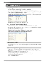
Page 66: ...of the CFD controller When shipping from out factory the RMU is disabled To use the RMU enable the RMU after connecting it to the CFD controller POINT If the RMU is not connected to the robot controller or the robot controller cannot recognize the RMU the setting screen to enable the RMU will not appear Next how to enable the RMU is described hereinafter To perform these setting operations the ope...

Page 67: ... the RMU is recognized by the robot controller 3 Change the setting for the Servo Amplifier 1 to Connect 4 Press f12 Complete The following screen will be displayed 5 After pressing any key turn OFF the power of the robot controller and then turn ON it 6 After restarting the robot controller setup the parameters referring to Chapter 4 Monitoring Unit Settings ...

Page 68: ...2 9 Enabling RMU 2 40 NOTE ...

Page 69: ...4 Tool limit setting 3 13 3 2 5 Arm limit setting 3 20 3 2 6 Other settings 3 22 3 2 7 VSF approach area output signal 3 23 3 2 8 Setting example of the limit line 3 24 3 2 9 Creation of data file 3 25 3 2 10 Convenient shortcut 3 25 3 3 List of Error Codes 3 26 3 4 Setting when a slider unit is used 3 27 3 4 1 Mechanism relation 3 27 3 4 2 Installation angle Example1 3 28 3 4 3 Installation postu...

Page 70: ......

Page 71: ...he data of motion limit area arm shape and tool shape defined in this VSF function are sent to the Robot monitoring unit RMU20 and the RMU20 also execute the monitoring in the same way with this robot controller Therefore when changing the setting for this VSF function do not forget to check the setting in the RMU20 and to execute the confirmation operation IMPORTANT This VSF function checks the p...

Page 72: ...inate system reference coordinate system Initial value 0 00 Y Vector Coordinate This is the Y coordinate of the mechanism coordinate system s origin based on the world coordinate system reference coordinate system Initial value 0 00 Z Vector Coordinate This is the Z coordinate of the mechanism coordinate system s origin based on the world coordinate system reference coordinate system Initial value...

Page 73: ...n place for the robot as Ground INFO Wall mount type setting example Set 90 deg for the Y axis rotation If necessary set the XYZ coordinates referring to the layout drawing In the screen of Mechanism relation set the installation place for the robot as Ground Do not select Wall INFO Ceiling mount type setting example Set 180 deg for the X axis rotation If necessary set the XYZ coordinates referrin...

Page 74: ...below will appear Table 3 2 2 Virtual Safety Fence Setting Items Menu Function Range setting Used to display the Setting screen to specify the safety fence area and the part range Furthermore this menu enables confirmation of all limit areas on the graphic display Tool limit setting Used to make setting of sphere cylinder and rectangular by tool Furthermore this menu enables confirmation of the se...

Page 75: ...piece arm reaches the limit range an error will occur This section defines the limit lines to specify the safety fence area and the part range The limit line settings are made by entering X Y coordinate values at two points 1 Open Constant Setting 3 Machine constants 33 Virtual Safety Fence 1 Range setting menu A screen like shown below will appear Part range Safety fence Safety fence Safety fence...

Page 76: ...ach time when the f key Fence Range and the f key Part Range are pressed the Range setting and Part setting screens are alternately switched 4 Press the f key Part Range No The following window will appear 5 Enter the desired Part Range No The displayed No on the f key will be changed 6 Press the f key Graphic Display The Graphic Display screen Top shown below will appear Fence Range ...

Page 77: ...y screen will be switched Each time when the f key Plane change key on the Graphic Display screen is pressed the screen will be switched from Top Side Rear Top in the order described For the Fence Range and Part Range menus the screen is switched in the same order as that aforementioned Top display Side display ...

Page 78: ...ar 10 Enter the desired Tool sphere No The displayed No on the f key will be changed 11 Press the f key Terminate The Graphic Display will be closed to return to the Range setting screen 12 After the completion of settings press the Complete Side Top Rear Z X Y Fig 3 2 1 Top Side and Rear Switching ...

Page 79: ... the line concerned Furthermore if the upper and lower limits in the Z direction are both 0 0 no regulations will be executed in the Z direction If the two coordinates at two points entered are the same if a distance from the line found by coordinates at two points and the home position is not more than 50 mm or if a value larger than the upper limit value is set to the lower limit value in the Z ...

Page 80: ...me positions as those of next start points The part range setting can be made with three points It can be set in the range of a triangle using three points or in the range of a box using four points POINT The following configurations are not available to settings 1 Limit lines need to be continued Putting different lines in the middle will disable setting 2 No limit line settings can be made using...

Page 81: ...r limit value varies with installation locations If A is set the lower limit value will come to 0 mm Fig 3 2 3 Typical Safety Fence Range Z Direction Upper and Lower Limit Values Safety Fence 1 Safety Fence 2 Safety Fence 3 Safety Fence 4 A A Lower limit value 800 mm Upper limit value 3000 mm ...

Page 82: ...3 2Operation procedure 3 12 Fig 3 2 4 Typical Part Ranges 1 to 3 Part Range 1 Part Range 2 Part Range 3 Part Range 2 Part Range 3 Part Range 1 ...

Page 83: ...t range an error will occur For a robot used for handling application it is recommended to use different tool numbers for operating the robot only for handling and for operating it with work piece Furthermore depending on with or without work piece make settings of sphere and form according to the work piece size 1 Open Constant Setting 3 Machine constants 33 Virtual Safety Fence 2 Tool limit sett...

Page 84: ...e f key Sphere Limit Each time when the f key Sphere Limit and the f key Form Limit are pressed the Sphere Limit and Form Limit screens are alternately switched 4 Press the f key Tool Number The following window will appear 5 Enter the desired Tool No The displayed No on the f key will be changed 6 Press the f key Page key The Sphere Limit Setting screen will be switched This screen is only displa...

Page 85: ...ne change The points of sight of the Graphic Display screen will be switched Each time when the f key Plane change key on the Graphic Display screen is pressed the screen will be switched from Top Side Rear Top in the order described For the Sphere Limit and Form Limit menus the screen is switched in the same order as that aforementioned Top Display Sphere Limit ...

Page 86: ...3 2Operation procedure 3 16 Top Display Form Limit Side Display Sphere Limit Side Display Form Limit ...

Page 87: ...ph The following window will appear 10 Enter the desired Tool sphere No The displayed No on the f key will be changed 11 Form Limit Press the f key Tool sph Every time this key is pressed the number will be changed 12 Press the f key Terminate The Graphic Display will be closed to return to the Range setting screen ...

Page 88: ...ss of rectangular If 0 0 is specified to all of the width thickness and height the rectangular concerned will be disabled Default value 0 0 Height H Used to specify the height of rectangular If 0 0 is specified to all of the width thickness and height the rectangular concerned will be disabled Default value 0 0 Form Rectangular Offset Used to specify a distance from the flange Default value 0 0 Gr...

Page 89: ...phere Setting Fig 3 2 6 Form Limit Setting Rectangular Height Thickness Width Used to make setting of distance from the center of the flange surface Radius Center Offset Used to make setting of distance from the center of the flange surface ...

Page 90: ...on of settings press the Complete Table 3 2 6 Items to be set on Arm Limit Setting Screen Parameter Function Radius Used to make setting of the radius of all axes Default value 0 0 Start X Y Z Used to define the start point of the arm Based on the robot coordinate system Default value 0 0 End X Y Z Used to define the end point of the arm Based on the robot coordinate system Default value 0 0 Axis ...

Page 91: ...ers based on the robot coordinate system origin And in this case the robot posture should be the Machine reference posture in which the all axes are set to the reference position Radius X Y Z X Y Z axis X Y Z Robot coordinate system origin X Z x y z 1200 0 2030 x y z 550 0 2030 Robot coordinate system origin A cylinder like this is defined Radius 150mm length 650mm ...

Page 92: ... limit range set and this margin is taken as the drawing range of the limit area which will be displayed on the graphic display screen Default value 0 0 Buzzer limit distance Used to make setting of distance at which the buzzer sounds While in TEACH mode when a limit object comes close to the limit range the buzzer of the teach pendant will keep sounding Default value 0 0 POINT Buzzer limit distan...

Page 93: ...the robot is located in the virtual safety fence 1 Open Constant Setting 6 Signal attributes 3 Output signal assignment 1 Standard Outputs The Menu screen shown below will appear 2 Put the cursor on the VSF approach area output signal enter any signal number and then press the ENTER key 3 After the completion of settings press the Complete ...

Page 94: ...ction shows a typical limit line setting 1 Make setting of movement area of the robot so that it will move in a circular pattern 2 Make setting so as to limit the robot movement to the front and the side 3 Make setting of further limit area to the movement area Movement area Limit area ...

Page 95: ... be turned OFF and ON again NOTE No file transfer by FTP is enabled 3 2 10 Convenient shortcut Entering the shortcut code R710 makes it possible to display the Virtual Safety Fence Menu screen However this function is available only in TEACH mode Entering the shortcut code R711 makes it possible to use the graphic display even during playback thus enabling confirmation of robot movement in the mov...

Page 96: ... The sphere defined on the tool pass across the border of limit area Countermeasures Move the robot to out of the limit area by manual in constant machine constant No 1171 Message Current position pass across the limit line Occurrence timing When any of the sphere form and arm limits is about to go beyond the movement limit area Possible causes The sphere defined on the tool pass across the border...

Page 97: ...ssary to setup the Mechanism relation and the Installation angle correctly Please be sure that when not correct the TCP position check cannot executed normally 3 4 1 Mechanism relation Constant Setting 12 Format and Configuration 9 Mechanism relation Place the robot M1 on the slider M2 Place the slider M2 on the Ground Ground M2 Slider M1 Robot ...

Page 98: ...r side Initial setting In this initial setting the relationship between the robot and the slider will be like the following picture The slider moves as Y axis direction linear joint Y Y X Slider position Slider position If the world coordinate system is selected in the manipulator M1 the values for the XYZRPY are displayed based on the world coordinate system Slider position ...

Page 99: ...round and the robot rotates against the parent mechanism slider Constant Setting 12 Format and Configuration 5 Installation Angle Robot side setting Slider side setting In this case the relationship between the robot and the slider will be like the following picture The slider moves as X axis direction linear joint Because the robot rotates on the slider its direction is like the following picture...

Page 100: ...3 4 Setting when a slider unit is used 3 30 NOTE ...

Page 101: ...s 4 21 4 3 4 Conformation of area parameters 4 22 4 3 5 Conformation of limit parameters 4 24 4 3 6 Conformation of stop parameters 4 26 4 3 7 Conformation of signal parameters 4 27 4 3 8 Confirmation of Logic parameters 4 29 4 3 9 Confirmation of Safety network parameter RMU20 30 4 30 4 3 10 Confirmation of Safety network parameter RMU20 40 4 31 4 4 Approval 4 32 4 4 1 Approval procedure 4 32 4 4...

Page 102: ......

Page 103: ...cted to the FD controller when shipping from our factory The RMU setting is enabled In case of the CFD controller When shipping from out factory the RMU is disabled To use the RMU enable the RMU after connecting it to the CFD controller In the following cases you will need to set up the RMU 1 When the RMU Robot monitoring unit has been replaced 2 When Memory format initialization Backup restore Co...

Page 104: ...DANGER Please make sure the parameter values are changed correctly in the confirmation screen of the parameter If the parameter is not set correctly the robot does not work in the intended function will be death or serious injury accidents 3 Approval 4 4Approval Confirm that the monitoring unit parameters and robot controller parameters are the same Robot can not be operated without approval Power...

Page 105: ...MU has been changed But this is normal If these settings have been modified perform an approval procedure for the RMU according to the following steps 1 Confirmation of parameters 4 3Confirmation of parameters Confirm the parameters which have been set DANGER Please make sure the parameter values are changed correctly in the confirmation screen of the parameter If the parameter is not set correctl...

Page 106: ...al Safety Fence Function all setting under were 3 Constants 2 machine constants 34 Robot monitoring unit all setting except 1 setting As for the tool constants refer to the instruction manual SETUP Chapter 4 Set up As for the Virtual Safety Fence Function refer to the instruction manual 尾 fRMU Advanced Operations Chapter 2 Virtual Safety Fence The following message is displayed when the above ment...

Page 107: ...er setting press f12 Complete When setting is done correctly following message is displayed But this is normal After closing this message with R key perform the confirmation operation Table 4 3 Mechanism parameters Parameter Function Default value TCP stop watch limit This is the error detection distance mm of the Stop monitoring 10 TCP speed level H 1 5000 TCP speed level H 2 0 TCP speed level H ...

Page 108: ...ence to the following table If there is no parameter to be updated following operation is necessary IMPORTANT If the RMU had been replaced or backup restore operation had been executed perform writing operation even if there are no modified parameters 3 After setting press f12 Complete When setting is done correctly following message is displayed But this is normal After closing this message with ...

Page 109: ...erence pulse of current position when stop monitoring input This parameter is set at the factory Speed limit 1 4 This is the ratio of abnormal speed rpm in high speed This parameter is set at the factory Upper Zone limit 1 4 Set the upper limit of the Zone limit deg or mm When Get origin is pressed the present position is set Lower Zone limit 1 4 Set the lower limit of the Zone limit deg or mm Whe...

Page 110: ...ed perform writing operation even if there are no modified parameters 3 After setting press f12 Complete When setting is done correctly following message is displayed But this is normal After closing this message with R key perform the confirmation operation Table 4 5 Axis parameters Parameter Function Default value Tool posture watch r p y theta 1 4 The reference posture and the allowable range o...

Page 111: ...ectly following message is displayed But this is normal After closing this message with R key perform the confirmation operation Table 4 6 Stop parameters Parameter Function Default value Free running time This is the free running time sec of the robot to stop This parameter is set at the factory Operator class SPECIALIST is necessary to change this parameter This value varies due to the robot typ...

Page 112: ... the Table 4 6 Signal parameters If there is no parameter to be updated following operation is necessary IMPORTANT If the RMU had been replaced or backup restore operation had been executed perform writing operation even if there are no modified parameters 3 After setting press f12 Complete When setting is done correctly following message is displayed But this is normal After closing this message ...

Page 113: ...1 4 This is to set the input signal number of AXES speed monitoring in playback 0 Zone limit sig 1 4 This is to set the input signal number of Zone limit signal in playback 0 Tool posture watch sig 1 4 This is to set the input signal number of Tool posture watch sig 0 Tool number input sig 1 5 This is to set the input signal number of Tool number input signal 1 2 3 4 5 Network logic condition Enab...

Page 114: ... above setting example is as follows General safety output 1 Internal relay Teach mode AND Internal relay Inside Part 2 OR Inside safe stop General safety output 2 Safety input relay Robot E STOP General safety output 3 Safety input relay Robot E STOP IMPORTANT If the RMU was replaced press the Complete key even if there are no changed parameters General safety output 1 General safety output 2 Gen...

Page 115: ...ing message is displayed But this is normal After closing this message with R key perform the confirmation operation For details of the logical operation relays see 2 7 Logical operation output function Supplement In case of RMU20 30 or RMU20 40 the Safety network output signals N1 N64 are also available ...

Page 116: ...llowing message is displayed But this is normal After closing this message with R key perform the confirmation operation Table 4 8 Setting items for the safety network parameters Parameter Description Default Safety inputs outputs This is a Disable Disable switch for the safety network function To use this function select Enabled Disabled IP Address This is the IP address that is used for the Ethe...

Page 117: ... key perform the confirmation operation Table 4 9 Setting items for the safety network parameters Parameter Description Default Safety inputs outputs This is a Disable Disable switch for the safety network function To use this function select Enabled Disabled Input bytes Set the input size of the I O in bytes This is fixed to 8 8 Output bytes Set the output size of the I O in bytes This is fixed t...

Page 118: ...ned in this section 1 Open Constants 3 machine constants 34 Robot monitoring unit 2 Confirmation If the setting has not been finished a following screen will be displayed In a case like this please execute Complete operation in the respective menu screens in advance of opening this Confirmation menu POINT This pop up message window will show up when trying to enter the Confirmation menu without co...

Page 119: ... Press Page scroll key All parameters are displayed on their order If there are plural mechanisms their parameters are displayed continuously 3 Check all parameters When all parameters are correct press OK key If wrong parameters are displayed please try to perform the writing procedure If some of them were incorrect even after writing procedure the RMU may malfunction Please consult with each NAC...

Page 120: ... of the mechanism parameter to define the arm length Offset angle One of the mechanism parameter to define the arm angle Machine type 1 Parameter to classify the mechanism type Wrist type Parameter to classify the wrist type Total axes Quantity of axis of the mechanism Installed angle Parameter to define the angle that mechanism is installed Amp No Amplifier number to which the mechanism is connec...

Page 121: ...s Page scroll key All parameters are displayed on their order If there are plural mechanisms their parameters are displayed continuously 3 Check all parameters When all parameters are correct press OK key If wrong parameters are displayed please try to perform the writing procedure If some of them were incorrect even after writing procedure the RMU may malfunction Please consult with each NACHI FU...

Page 122: ...et Encoder offset parameter Lower soft limit Software limit of lower side Upper soft limit Software limit of upper side Encoder type Parameter to define the encoder type Radians pulse Parameter to define the pulse count per one rotation of encoder Std pos Enc Encoder data of reference position for each axis Std Pos Angle Angle of reference position for each axis Connection Parameter to connect or ...

Page 123: ...nd Tool posture watch When all parameters are correct press OK key If wrong parameters are displayed please try to perform the writing procedure If some of them were incorrect even after writing procedure the RMU may malfunction Please consult with each NACHI FUJIKOSHI service office Table 4 9 Tool parameters Parameter Function Length xyz 1 32 TCP position mm Tool posture watch r p y theta 1 4 Par...

Page 124: ...a Change key Parameters are displayed on their order 3 Check all parameters for operation area When all parameters are correct press OK key If wrong parameters are displayed please try to perform the writing procedure If some of them were incorrect even after writing procedure the RMU may malfunction Please consult with each NACHI FUJIKOSHI service office 4 Press Area Change key The following scre...

Page 125: ...ted area Fence range Z range upper Parameter to define the height of Fence range This is the upper limit Fence range Z range lower Parameter to define the height of Fence range This is the lower limit Exit permit signal This is a signal that is required to be ON when the robot is trying to go outside of the range Part range Line 1 to 4 Inside the area defined by maximum of 4 lines from the center ...

Page 126: ...ters are displayed please try to perform the writing procedure If some of them were incorrect even after writing procedure the RMU may malfunction Please consult with each NACHI FUJIKOSHI service office 4 Press Limit Change key The following screen will be displayed 5 Check all parameters for arm limit data When all parameters are correct press OK key If wrong parameters are displayed please try t...

Page 127: ... center position of sphere that means the tool area Joint Joint number with which robot arm synchronizes Cylinder 1to 10 Radius Parameter to define the size of cylinder that means the robot arm area Cylinder 1to 10 Start xyz Parameter to define the starting position of cylinder that means the robot arm area Cylinder 1to 10 End xyz Parameter to define the ending position of cylinder that means the ...

Page 128: ...e correct press OK key If wrong parameters are displayed please try to perform the writing procedure If some of them were incorrect even after writing procedure the RMU may malfunction Please consult with each NACHI FUJIKOSHI service office Table 4 15 Stop parameters Parameter Function Free running time Parameter to define the free running time sec of the robot to stop Braking deceleration Paramet...

Page 129: ...rmation 7 Signal parameters The following screen will be displayed 2 Check all parameters When all parameters are correct press OK key If wrong parameters are displayed please try to perform the writing procedure If some of them were incorrect even after writing procedure the RMU may malfunction Please consult with each NACHI FUJIKOSHI service office ...

Page 130: ...l number of Robot selection signal TCP Speed watch signal 1 4 This is to set the input signal number of TCP speed monitoring in playback AXES speed watch signal 1 4 This is to set the input signal number of AXES speed monitoring in playback Zone limit sig 1 4 This is to set the input signal number of Zone limit signal in playback Tool posture watch sig 1 4 This is to set the input signal number of...

Page 131: ...rmation 8 Logic parameters The following screen will be displayed 2 Check all parameters When all parameters are correct press OK key If wrong parameters are displayed please try to perform the writing procedure If some of them were incorrect even after writing procedure the RMU may malfunction Please consult with each NACHI FUJIKOSHI service office ...

Page 132: ...ot monitoring unit 2 Confirmation 9 Safety network parameters The following screen will be displayed 2 Check all parameters When all parameters are correct press OK key If wrong parameters are displayed please try to perform the writing procedure If some of them were incorrect even after writing procedure the RMU may malfunction Please consult with each NACHI FUJIKOSHI service office ...

Page 133: ...ot monitoring unit 2 Confirmation 9 Safety network parameters The following screen will be displayed 2 Check all parameters When all parameters are correct press OK key If wrong parameters are displayed please try to perform the writing procedure If some of them were incorrect even after writing procedure the RMU may malfunction Please consult with each NACHI FUJIKOSHI service office ...

Page 134: ...l How to perform approval is explained in this section 4 4 1 Approval procedure 1 Open Constant Setting 3 Machine constants 34 Robot monitoring unit 3 Approval When conformation of all parameter is completed following screen will be displayed RMU ID number is 0 This means approval is not completed When confirmation of some parameters is not completed following screen will be displayed Item of whic...

Page 135: ... be displayed The following screen will be displayed Now controller ID and RMU ID become the same Approval is completed 4 After closing the screen with R key on the teach pendant reset the error To make the error reset operation press R key 2 times When the error message E1107 Robot monitoring unit is not approved disappears and OK is displayed the reset work is completed ...

Page 136: ...FDV4 14 or after 0 Change the operator class to EXPERT or higher 1 Open the Constant setting 3 Machine constant 34 Robot Monitoring Unit 2 Press f8 key The following screen will be displayed 3 Press the Execute The following screen will be displayed The setting operation for the items that have not been set will be executed automatically The finished item is displayed with a check mark If the appr...

Page 137: ... OK key NOTE The unfinished screens will appear one after another Check the parameters in the same way and press OK respectively 6 After the confirmation operation is finished proceed with the approval operation A screen like the following will be displayed 7 Input the password to finish the approval The following screen will be displayed Now controller ID and RMU ID become the same Approval is co...

Page 138: ...4 4Approval 4 36 8 Approval is completed The following screen will be displayed ...

Page 139: ...coming into contact with or getting caught in the robot will result in death or serious injury And after using the Axial separation menu do not forget to make the setting that was changed here to the original setting If this is forgotten the robot may not work normally 4 5 1 Setting of disconnection 1 SPECIALIST or higher operator class is necessary to change this parameter 2 Open Constants 3 Mach...

Page 140: ... displayed When disconnected axis is correct press OK Then setting will be started When setting is done correctly following message is displayed But this is normal Close this message with R key Proceed with the certifying procedure 5 If the connection setting is changed turn OFF and ON the controller power ...

Page 141: ...ng Setting menu Description Remark Constant Setting 3 Machine constants 5 Soft limit Software limit setting screen 4 6 3 Speed monitoring Table 4 19 Settings for speed monitoring Setting menu Description Remark Constant Setting 3 Machine constants 34 Robot monitoring unit 1 Settings 1 Mechanism parameters TCP speed level H TCP speed level H can be set Constant Setting 3 Machine constants 34 Robot ...

Page 142: ... this value here Constant Setting 3 Machine constants 34 Robot monitoring unit 1 Settings 7 Signal parameters Tool watch Disable Enable the tool number watching function 4 6 6 Safety network parameters RMU20 40 Table 4 22 Settings for safety network parameters Setting menu Description Remark Constant setting 8 Communication 3 Fieldbus The communication parameters for the PROFINET Slave are set her...

Page 143: ...ine of the EtherNet IP safety network function 5 1 5 2 Setting for RMU 5 2 5 2 1 Safety network parameter 5 2 5 2 2 Assignment of the network I O signals 5 2 5 3 Settings for the safety PLC 5 4 5 3 1 Setting procedure 5 4 5 4 Trouble shooting 5 9 5 4 1 Trouble shooting via the LEDs 5 9 5 4 2 Error codes 5 9 ...

Page 144: ......

Page 145: ... The RMU20 30 works as an adopter for safety PLC like Rockwell GuardLogix etc IMPORTANT When using the EtherNet IP Safety communication function please do not forget to turn OFF and ON the power after changing the setting of the RMU and completing the approval operation for the RMU even if there is no modification about the Safety network parameters Because the communication will not start unless ...

Page 146: ...nitoring Unit 1 Settings 7 Signal parameters For details refer to 4 2 4 Setting of signal parameters In this section the specific functions that use the network signals are explained Those functions can be assigned to the network signals in the following screen Network logic condition This is a software switch to decide if the Motors ON condition is included to the logical operation of the safety ...

Page 147: ...led Network remote mode signal It is possible to change the robot controller s operation mode using the safety network signals The operation mode can be changed using the combination of the following signals NetWork remote sig Network remote mode signal NetWork Ext teach sig Network external TEACH signal NetWork Ext playback sig Network external PLAYBACK signal NetWork Ext H teach sig Network exte...

Page 148: ...RSLogix5000 2 Select the Controller project of the network to which the RMU is added To create new one select New in the File menu If a communication module is not installed in the Bus of the I O Configuration add a communication module e g 1768 ENBT etc 3 Right click the Tasks SafetyTask of the Controller Organizer and then select the Properties The following screen will show up 4 Select the Conf...

Page 149: ...n name Description Write descriptions freely IP address Set the IP address of the RMU 8 Make the setting of network parameters Press the Change button Set the following values Item Value Vendor 441 Product Type 140 Product Code 1 Major revision 1 Minor revision 1 Electric Keying Exact Match Input Data Safety Output Data Safety Data Format Integer SINT ...

Page 150: ... in the Safety Output Size Safety Output Size Set the size of the output data Because this is the setting of the output from the PLC set the value of Input bytes of the RMU Configuration Assembly Instance 1024 Press the OK button 10 Select the Safety tab The following screen will show up Set a value of 50ms or more for the Safety Input Requested Packet Interval RPI ms Turn OFF the check box of Con...

Page 151: ... PLC Select Who Active from the Communications menu The following screen will be displayed Select the PLC and press Go Online POINT If a message like The project of the RSLogix500 and the Safety PLC does not match is displayed please download the project to the Safety PLC 13 Make the setting of the SNN Safety Network Number Right click the added ETHERNET SAFETYMODULE Name and select the Properties...

Page 152: ... SNN Safety Network Number is set and the communication will start POINT If the Set button cannot be pressed please check that the RMU is connected to the network And if the Safety Network Number is already set the same thing will occur In this case reset the Safety Network Number if necessary The reset operation can be executed by pressing the Reset Ownership button in the Safety tab ...

Page 153: ... the Safety PLC is setting the SNN Waiting for the connection LED4 flashing Green See Table 5 4 2 Waiting for the connection from the Safety PLC Communicating LED4 ON Green LED6 ON Green Connected to the Safety PLC and the communication is beging performed Fault LED5 flash or ON Red See Table 5 4 2 This occurs when a connection was made from a safety PLC in which a different SNN is set Set the SNN...

Page 154: ...5 4Trouble shooting 5 10 NOTE ...

Page 155: ...f the PROFINET safety network function 6 1 6 2 Setting for PROFINET module 6 2 6 2 1 Fieldbus settings 6 2 6 2 2 Setting for the PROFINET Safety 6 4 6 3 Safety network parameters 6 6 6 3 1 Assignment of the network I O signals 6 6 6 4 Trouble shooting 6 8 6 4 1 Trouble shooting via the LEDs 6 8 6 4 2 Error codes 6 9 ...

Page 156: ......

Page 157: ...it is possible to input emergency stop signal etc that require doubled redundant wirings or safety relays etc through only 1 network cable and reduce the amount of connections wirings In this PROFINET Safety function this robot controller works as a Safety device SLAVE for the PLC To use this PROFINET Safety function in this controller not only RMU20 40 but also PROFINET communication modules FD11...

Page 158: ...fety and press Enter key Select the PROFINET Safety using the cursor key and press Enter key 3 Align the cursor with the Slot ID combo box and press Enter key Select the Slot ID where PROFINET board is mounted and press Enter key The slot ID is required in order to check the position where the board has been installed Concerning the relationship between the slot position and the slot ID refer to t...

Page 159: ...6 3 4 Align the cursor with the edit box of the module Input the applicable module number and press Enter key The module number is necessary to confirm the installed position on the FIELDBUS base board module ID Now proceed to set the PROFINET safety 2 1 ...

Page 160: ...st have the same setting values for this subnet mask Default gateway Input the IP address of the Default gateway for the concerned node This setting may not be necessary if a router does not exist in the network Please consult with the network administrator and set this parameter if necessary INPUT BYTES Set the INPUT BYTES from the Master device to this controller SLAVE device 8 points are includ...

Page 161: ...o not change the settings of this controller from the external devices when the robot and its peripheral devices etc are running Because the settings are changed while the robot is running unexpected and dangerous accidents may occur due to the change of the I O conditions 3 After finishing the settings press OK The screen will return to 3 Fieldbus 4 Press Complete in 3 Fieldbus screen The setting...

Page 162: ...is designed intending that the minimum watch dog time is 70ms But there is a possibility that the communication speed cannot work in time depending on the network configuration Please set the appropriate watch dog time without fail considering the configuration of the network and perform the risk assessment for the parameter 6 3 1 Assignment of the network I O signals In the I O signal assignment ...

Page 163: ...op signal can be enabled disabled using the setting item of Teach protect stop For details refer to 4 2 4 Setting of signal parameters If 0 is set this function is disabled Network external enable signal By assigning this signal it becomes possible to get the external enable input signal from the safety network If this signal is not ON the Motors cannot be turned ON in the TEACH mode If 0 is set t...

Page 164: ...e replace the PCB Red Flashing DCP Signal DCP Signal was received from the master device LED2 Unlit Normal No error Red Lit Connection failed Not connected or the network communication speed is not fast enough Please check the network cables etc Red Flashing No data communication No I O communication Please check that the PROFINET Controller is working normally LED3 Unlit Normal No error If the al...

Page 165: ...codes No E1116 Message Communication fault in the Safety network communication was detected Cause Communication fault in the Safety network communication was detected Remedy Please check if the network or the master device has no problem ...

Page 166: ...6 4Trouble shooting 6 10 NOTE ...

Page 167: ...1 1 Inspection schedule 7 2 7 1 2 Routine inspection items 7 2 7 1 3 Periodic inspection items 7 3 7 1 4 Replacing of the RMU 7 4 7 2 Troubleshooting 7 5 7 2 1 Example of trouble shooting 7 16 7 2 2 Procedures to be performed after encoder replacement work 7 16 7 2 3 Trouble shooting example for input signal inconsistency failure 7 19 ...

Page 168: ......

Page 169: ...G terminal of the controller electrically shorted to set them to the same potential ex Using an earthing band Electric shocks can result in serious injury or death WARNING A large number of connectors are connected to the RMU When replacing parts proceed carefully to ensure that the connectors are not connected incorrectly and that none of the connectors are left unconnected Electric shocks and th...

Page 170: ...0H 5000H 3000H 3 month inspection 3 month inspection 3 month inspection 6 month inspection Annual inspection 6 month inspection Annual inspection 3 month inspection 6 month inspection 7 1 2 Routine inspection items As a routine check item check whether dust and dirt have built up in the RMU WARNING Allowing dust and dirt to build up in the RMU may cause electrical short circuiting and other proble...

Page 171: ...Displays Inspection location Details of inspection Remedial action RUN LED 7 segments Check that the LED is lighted as if to describe the number 8 If an error is displayed proceed with troubleshooting 3 Installation and connection statuses Inspection location Details of inspection Remedial action Installation of unit Check that the RMU is installed properly inside robot controller Install it prope...

Page 172: ...ic shocks or unexpected movements of the robot which can pin an operator cause death or serious injury Required tool screw Detaching of the RMU 1 Turn off the controller power 2 Remove all connectors connected to the RMU 3 Loose the fixing screws and detach the RMU Installing of the RMU 1 Tighten the screws of the RMU to fix it on the bracket 2 Connect all connectors of the RMU 3 Turn on the contr...

Page 173: ...rned OFF The emergency stop output depends on the status of the emergency stop signal Check if an error of E51 Encoder data transmission error occured at the same time If it has occured encoder wire or the drive unit may be wrong Please check the connection of the robot internal wiring and the wire harness Or repleace the drive unit If it has not occured please check the wiring to the RMU And chec...

Page 174: ...it in constant mode the input Motors ON while holding down the LS release SW LSSW in the robot controller Move the robot inside the operating range The LS release switch LSSW must be held down until the robot is moved within the operating range There is no need to turn off on the power The location of the LS relase SW LSSW is shown in the controller maintenance manual Assist code SUB1 Description ...

Page 175: ...d angle monitoring function In playback operation if this error occurs when the robot is in the controlled area please perform the program modification like the following Move the recorded point position inside the controlled area Slow down the recorded speed Make the controlled area size larger Assist code SUB1 Assist code SUB2 Assist code SUB3 Description Border line No Tool sphere No This shows...

Page 176: ...xis s speed exceeds the setting value 3 Playback speed of the TCP exceeds the setting value Assist code Error Error code Top Controller Bottom RMU SUB1 SUB2 SUB3 Description of trouble Remedy 1 No Approval 2 Parameter error No Approval E1107 E05 3 Safety fence data error This error occurs if master ON is initiated when the approval work has not been carried out after the parameters have been rewri...

Page 177: ...e switch signal 4 Safety input 3 Over current occured in the Slave error signal 8 Safety input 4 Over current occured in the Robot LS detection signal 16 Safety input 5 Over current occured in the Emergency stop signal 32 Safety input 6 Over current occured in the Safety plug signal 64 Safety input 7 Over current occured in the Protective stop signal 16 128 Safety input 8 Over current occured in t...

Page 178: ... 2 3 2 safety inputs table 2 10 for the detail of safety input signals Assist code SUB1 Assist code SUB2 Assist code SUB3 Description 1 Safety input 1 Robot emergency stop signal is inconsistent 2 Safety input 2 Enable switch signal is inconsistent 4 Safety input 3 Slave error signal is inconsistent 8 Safety input 4 Robot LS detection signal is inconsistent 16 Safety input 5 Emergency stop signal ...

Page 179: ...e axis that has moved is displayed The detection triger Magnet pole position 48 TCP position moved This is displayed when the TCP has moved in the stop monitoring Assist code Error Error code Top Controller Bottom RMU 1 2 3 Description of trouble Remedy Tool monitoring error E1114 E12 Tool 1 Program tool No Tool 2 Signal from the tool This error occur when the tool number is unmatch and the tool c...

Page 180: ...e motor pole position moves and the encoder position does not move this error occurs 48 1st axis 55 8th axis 64 71 If a failure happen in the pole position detection circuit this error occurs 64 1st axis 71 8th axis Assist code Error Error code Top Controller Bottom RMU SUB1 SUB 2 SUB 3 Description of trouble Remedy Position monitoring disparity error E1111 E10 This error occurs if there is too gr...

Page 181: ...stic for the safety output 2 is not finished normally 17 20 22 25 This error occurs if the output diagnostic for the safety output 3 is not finished normally Internal error Safety output 2 4 E1106 E23 E25 23 25 33 36 38 41 This error occurs if the output diagnostic for the safety output 3 is not finished normally Check if the wiring of the safety output 2 4 is normally connected Turn OFF and ON th...

Page 182: ... memory E1106 E30 32 30 32 This error occurs if the storage memory for the parameters does not work normally Turn OFF and ON the controller power Replace the RMU Assist code Error Error code Top Controller Bottom RMU SUB1 SUB 2 SUB 3 Description of trouble Remedy Internal error Serial communication E1106 E33 35 33 35 This error occurs if the serial communication in the RMU does not work normally T...

Page 183: ...MU Assist code Error Error code Top Controller Bottom RMU SUB1 SUB 2 SUB 3 Description of trouble Remedy Internal error CPU E1106 E40 40 This error occurs if a failure happens in the diagnostic for the CPU of the RMU Turn OFF and ON the controller power Replace the RMU Assist code Error Error code Top Controller Bottom RMU SUB1 SUB2 SUB3 Description of trouble Remedy Communication stop E1108 This ...

Page 184: ...ction values to calculate the robot position E1102 may happen if the encoder correction values are not correct Before moving the robot do not forget to perform the encoder correction work After completing the encoder correction work this message will appear But this is normal Please proceed with the following steps 3 Open Constant 3 Machine constants 34 Robot monitoring unit 2 Confirmation 2 Axes ...

Page 185: ...4 Robot monitoring unit 3 Approval When confirmation of all parameters is completed following screen will be displayed RMU ID number is 0 This means approval is not completed 7 Press Execute key Dialog to request the password is displayed at the bottom of screen ...

Page 186: ...ompleted 10 Turn OFF and ON the controller power POINT If encoder correction cannot be executed in the reference position or E1102 occurs please follow these steps to change the robot posture and make the robot return to its reference posture 1 Open Constant 3 Machine constants 33 Virtual Safety Fence 1 Range setting and turn the Motors ON with pressing the LSSW in the controller Concerning the lo...

Page 187: ... is inconsistent 64 Safety input 7 Protective stop signal is inconsistent 16 128 Safety input 8 External enable signal is inconsistent 1 Safety input 9 General input 1 signal is inconsistent 2 Safety input 10 General input 2 signal is inconsistent 4 Safety input 11 General input 3 signal is inconsistent 8 Safety input 12 General input 4 signal is inconsistent 48 16 Safety input 13 General input 5 ...

Page 188: ...on of the operation panel or the teach pendant and then check the LED PD4 PD5 of UM367 Was the error released Replace the I O board UM367 10 Was the error released NO NO Does the ON OFF condition match YES Was the error released Replace the Teach pendant or the operation panel NO Was the error released Replace the RMU and make the setting check and approvement NO Was the error released The interna...

Page 189: ......

Page 190: ...hone 420 255 734 000 Fax 420 255 734 001 Obchodni 132 251 01 Cestlice PRAGUE EAST CZECH REPUBLIC NACHI AUSTRALIA PTY LTD http www nachi com au Robotic Division Victoria office Phone 61 0 3 9796 4144 Fax 61 0 3 9796 3899 38 Melverton Drive Hallam Victoria 3803 AUSTRALIA Sydney office Phone 61 0 2 9898 1511 Fax 61 0 2 9898 1678 Unit 1 23 29 South Street Rydalmere N S W 2116 AUSTRALIA Brisbane office...

Reviews: