1.1 Outline
1-16
1.3.5 Connection of safety outputs
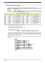
The general safety output signals should be connected to CNGP2 connector of RMU.
Electrical
specifications for
each outputs
FET output
DC30V
,
100
m
A max
Please be sure to make the connections so that the total current amount of the all outputs
(2ch x 3 outputs) is 600mA or less.
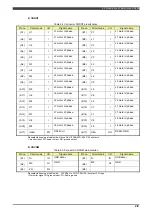
Table 1-7 CNGP2 connector pin layout
Pin No.
Marking
I/O
Signal name
Pin No.
Marking
I/O
Signal name
(A1) OUT2A+ SO
General safety output 11+
(B1) OUT2A- SO
General safety output 11-
(A2) OUT2B+ SO
General safety output 12+
(B2) OUT2B- SO
General safety output 12-
(A3)
BK2+
BI
Back check 1+
(B3)
BK2-
BI
Back check 1-
(A4) OUT3A+ SO
General safety output 21+
(B4) OUT3A- SO
General safety output 21-
(A5) OUT3B+ SO
General safety output 22+
(B5) OUT3B- SO
General safety output 22-
(A6)
BK3+
BI
Back check 2+
(B6)
BK3-
BI
Back check 2-
(A7) OUT4A+ SO
General safety output 31+
(B7) OUT4A- SO
General safety output 31-
(A8) OUT4B+ SO
General safety output 32+
(B8) OUT4B- SO
General safety output 32-
(A9)
BK4+
BI
Back check 3+
(B9)
BK4-
BI
Back check 3-
(A10)
(B10)
SO:Safety outputs, BI: Back check inputs
Cable side applicable receptacle housing:
Tyco electronics type:
2-1318118-9, 20pins, Y-type
Cable side connection terminal:
Tyco electronics type
1318108-1
(Applicable wire AWG#28-24) crimping tool type 91576-1
1318107-1
(Applicable wire AWG#22-18) crimping tool type 91595-1
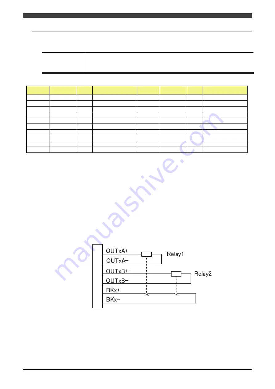
Safety relays or magnet switches that are equipped with force guide structure should be used for the
respective output circuits. And, please use the "b contact" also as a feedback signal to detect the malfunction of
the safety relays or the magnet switches. The "b contact" of the safety relays or magnet switches must be
connected to the back check inputs in series.
(NOTE) If the back check signal inputs are not inputted, a back check error will occur when the output signal is
turned ON.
Connector
Summary of Contents for RMU20-20
Page 2: ......
Page 6: ...Contents 4 ...
Page 8: ......
Page 26: ...1 4 EC DECLARATION OF CONFORMITY FOR MACHINERY 1 18 NOTE ...
Page 68: ...2 9 Enabling RMU 2 40 NOTE ...
Page 70: ......
Page 100: ...3 4 Setting when a slider unit is used 3 30 NOTE ...
Page 102: ......
Page 138: ...4 4Approval 4 36 8 Approval is completed The following screen will be displayed ...
Page 144: ......
Page 154: ...5 4Trouble shooting 5 10 NOTE ...
Page 156: ......
Page 166: ...6 4Trouble shooting 6 10 NOTE ...
Page 168: ......
Page 189: ......


