2.3 Connected signals
2-21
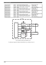
24V
内部回路
P1
GPINx
SW
R
RMU20
診断回路
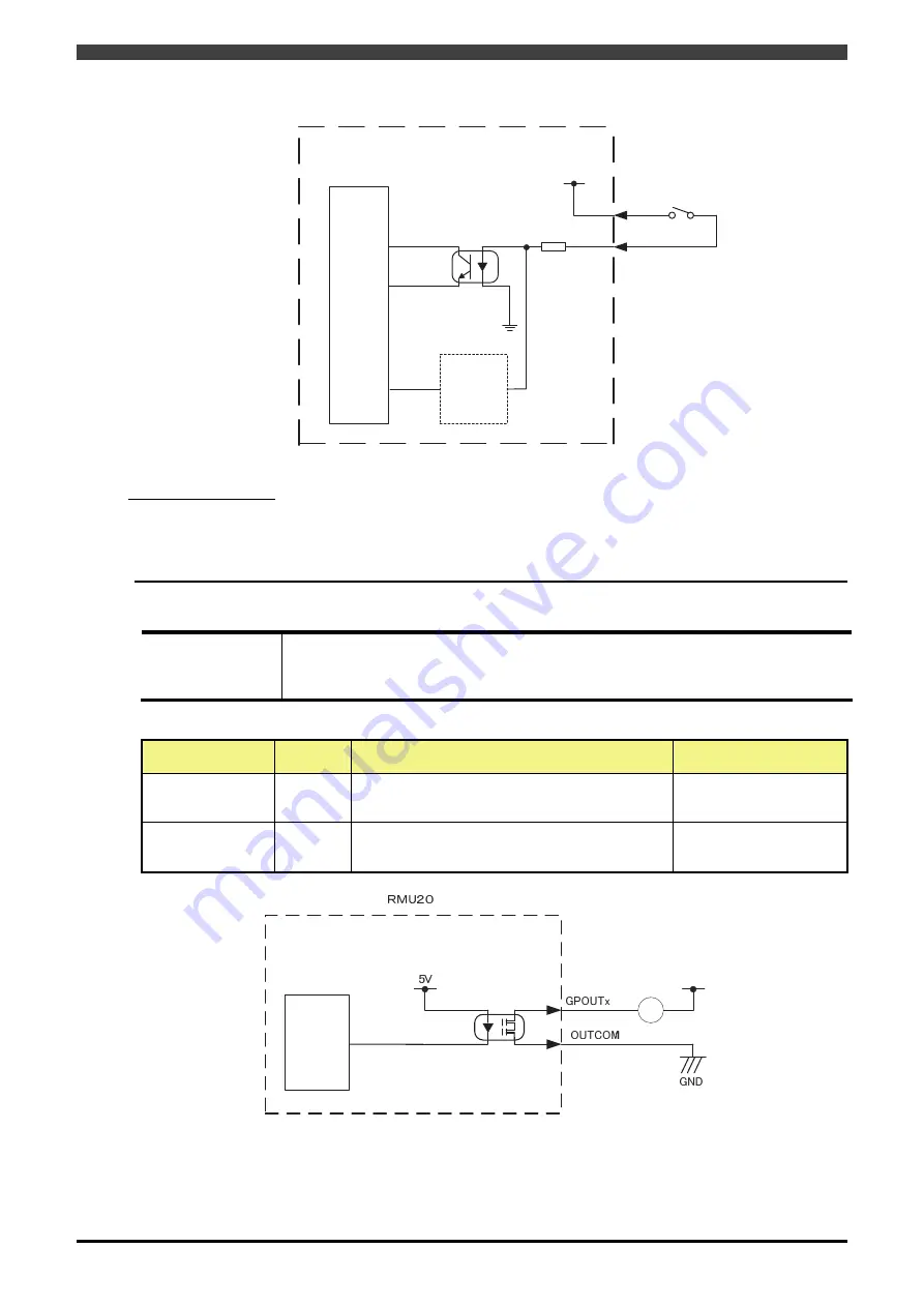
Fig. 2-6 Example of monitor input circuit
Input signal diagnosis
To detect trouble occurring in the input device, the same input signal diagnosis as for the safety input circuit is
performed. The internal circuit is diagnosed at periodic intervals by the diagnosis circuit. If error has been
detected by this diagnosis, the “Internal error: Input signal” is detected and the safety output is turned OFF. Error
is not reset unless the controller power is turned off and on.
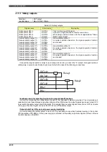
2.3.6 Monitor outputs
Electrical output
specifications
Photo MOS relay output
DC30V, 100mA
Install a surge absorption circuit without fail when a coil circuit such as a relay is to be
connected.
Table 2-17 Monitor outputs
Signal name
Circuit
code
Description
Electrical specifications
ES error
GPOUT1
This signal is connected to the controller input.
This signal is turned OFF when monitoring unit
detects an internal fault.
Photo MOS relay output
Rating
DC30V less than 100mA
Motors ON lamp
GPOUT2
This signal is output for the Motors-ON LED.
Photo MOS relay output
Rating
DC30V less than 100mA
Fig. 2-7 Example of monitor output circuit
Internal circuit
Diagnosis
circuit
Internal circuit
Load
External
24V
Summary of Contents for RMU20-20
Page 2: ......
Page 6: ...Contents 4 ...
Page 8: ......
Page 26: ...1 4 EC DECLARATION OF CONFORMITY FOR MACHINERY 1 18 NOTE ...
Page 68: ...2 9 Enabling RMU 2 40 NOTE ...
Page 70: ......
Page 100: ...3 4 Setting when a slider unit is used 3 30 NOTE ...
Page 102: ......
Page 138: ...4 4Approval 4 36 8 Approval is completed The following screen will be displayed ...
Page 144: ......
Page 154: ...5 4Trouble shooting 5 10 NOTE ...
Page 156: ......
Page 166: ...6 4Trouble shooting 6 10 NOTE ...
Page 168: ......
Page 189: ......


