Page-9
■
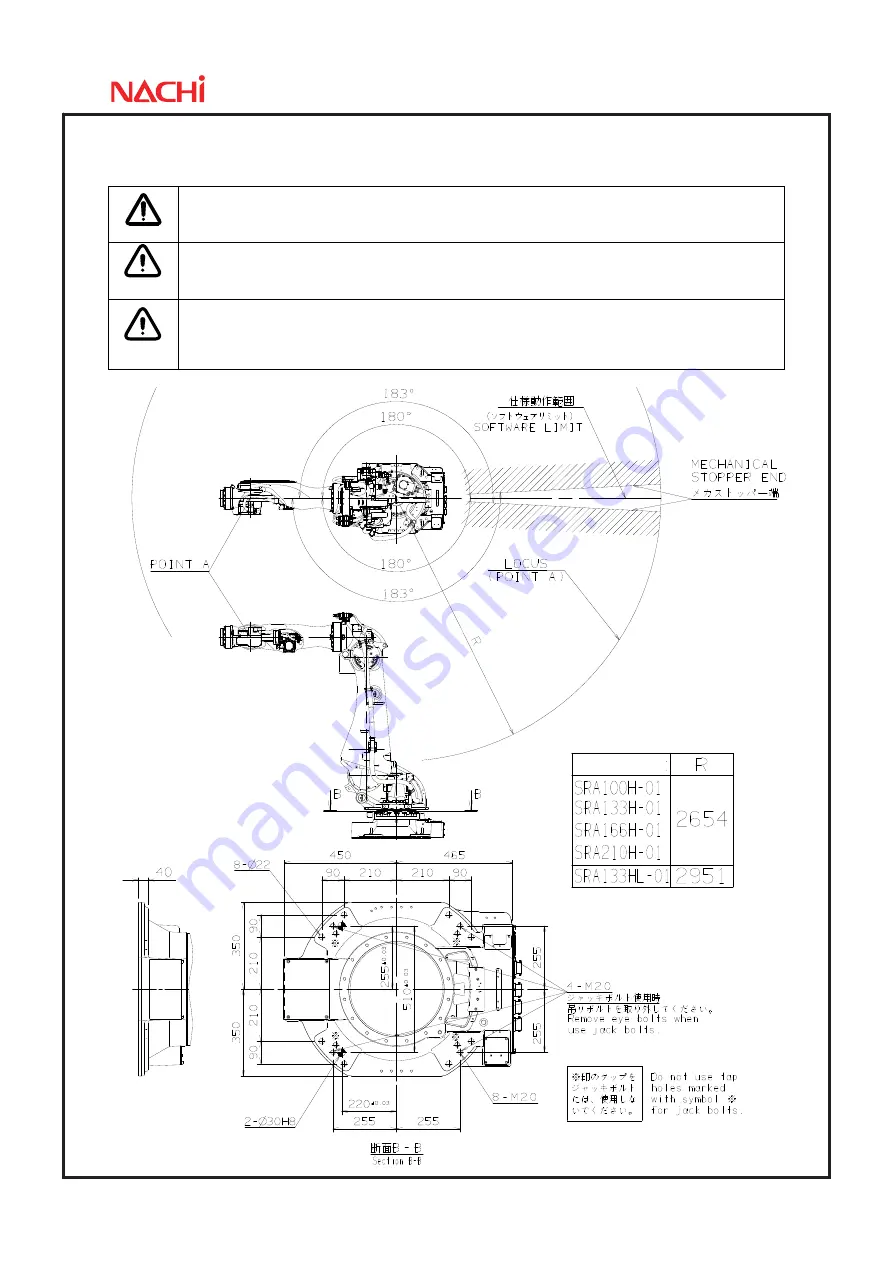
Installation space
To install the robot, lock the swiveling base of the robot.
CAUTION
The mechanical stopper end is located in a position exceeding the specified working
envelope (software limit) of axis 1 by 3
°
. To install the safety fence, with consideration
given to the wrist configuration and the shape of end effecter.
WARNING
On axes 1, 2 and 3, the robot working envelope can be regulated for safety (optional
function). Since optional parts should be installed to enable this function, do not
independently move the standard parts (e.g. mechanical stopper).
WARNING
If mechanical stopper collides and robot stops, it’s possible that some parts are already
damaged, for example, mechanical stopper is transformed or fixing bolts are broken. In
this case, sufficient intensity and function can not been kept. Mechanical stopper and
reduction gear of collided joint are needed to be replaced to the new one.
Robot type
Summary of Contents for SRA-H Series
Page 1: ...Standard specifications SRA H 01 FD11 SRA HL 01 FD11 6th edition 1608 SSRAEN 071 006 001 ...
Page 5: ...Page 3 3 Robot dimensions and working envelope SRA100H 01 SRA133H 01 ...
Page 6: ...Page 4 SRA166H 01 SRA210H 01 ...
Page 7: ...Page 5 SRA133HL 01 ...
Page 14: ...Page 12 SRA166H 01 SRA210H 01 ...
Page 16: ...Page 14 SRA166H 01 SRA210H 01 Axis 4 5 Axis 6 Axis 4 5 Axis 6 ...
Page 19: ...Page 17 SRA133HL 01 When wrist load is 133kg ...
Page 29: ......


