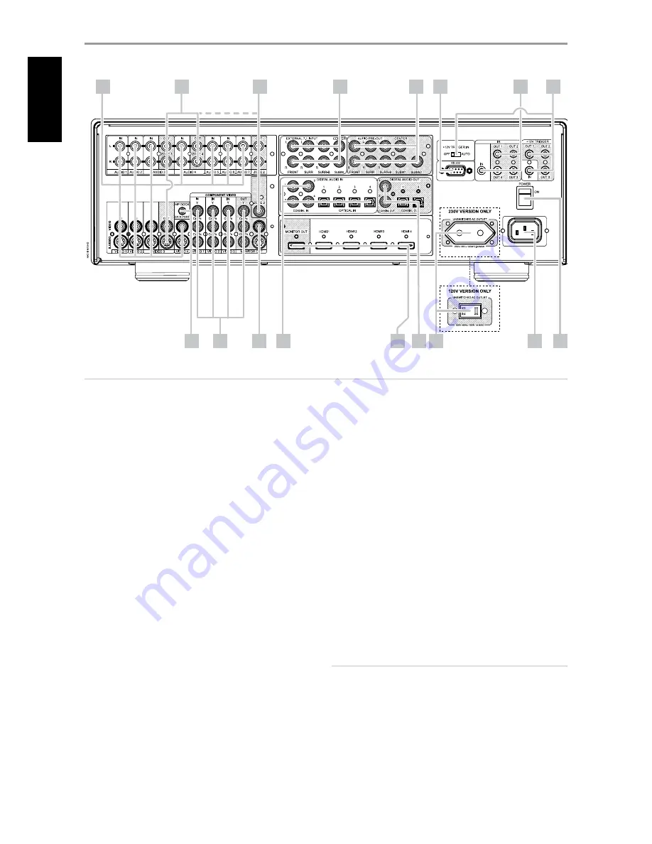
1 AUDIO 1-7 IN/VIDEO 1-4 IN/S-VIDEO 1-4 IN:
These comprise the
M15 HD’s principal input. Connect S-Video, composite video, and
analog stereo audio input ports to source components such as DVD
players and HDTV/satellite tuners.
AUDIO 3-4 IN/VIDEO 3-4 IN/S-VIDEO 3-4 IN may be used with recording
components such as videocassette or DVD-recorders by connecting
these components’ record-output to the corresponding M15 HD AUDIO
3 IN/VIDEO 3 IN/S-VIDEO 3 IN or AUDIO 4 IN/VIDEO 4 IN/S-VIDEO 4 IN
jacks. AUDIO 3 IN/VIDEO 3 IN/S-VIDEO 3 IN or AUDIO 4 IN/VIDEO 4 IN/S-
VIDEO 4 IN may freely be used for play-only components, in which case
their corresponding OUT jacks would remain unconnected. Refer also
to AUDIO 3 OUT/ VIDEO 3 OUT/S-VIDEO 3 OUT, AUDIO 4 OUT discussion
below.
AUDIO 6 and 7 are ideal for the connection of the analog output of line-
level audio sources like a CD player or Stereo tuner.
2 AUDIO 3 OUT/VIDEO 3 OUT/S-VIDEO 3 OUT, AUDIO 4 OUT:
Connect the M15 HD’s AUDIO 3 OUT/ VIDEO 3 OUT/S-VIDEO 3 OUT
or AUDIO 4 OUT ports to the analog audio/video input of recording
components such as cassette deck, DVD recorder or an outboard audio/
video processor. Connect the M15 HD’s AUDIO 3 IN/VIDEO 3 IN/S-VIDEO
3 IN or AUDIO 4 IN/VIDEO 4 IN/S-VIDEO 4 IN ports to the component’s
corresponding output.
The signal present at these M15 HD AUDIO/VIDEO OUT jacks is
determined by the source last selected via the front panel Source
keys or the HTRM’s input select keys with the exception of Source 3 or
Source 4. There will be no output at AUDIO 3 OUT/VIDEO 3 OUT/S-
VIDEO 3 OUT when Source 3 (AUDIO 3 IN/VIDEO 3 IN/S VIDEO 3 IN)
is selected. Likewise, there will be no output at AUDIO 4 OUT when
Source 4 (AUDIO 4 IN/VIDEO 4 IN/S VIDEO 4 IN) is the active source
input. This prevents feedback through the recording component
thereby preventing possible damage to your speakers.
When configured, AUDIO 3 OUT/VIDEO 3 OUT/S-VIDEO 3 OUT and
AUDIO 4 OUT are the same assigned ports for Zone 3 and Zone 4
respectively. See also Zone output description below.
3 ZONE 2, ZONE 3, ZONE 4:
Sends zone selected audio and video
output sources to the corresponding audio and video input of another
separate zone. Use high quality patch cables to reduce noise pickup
over long distance runs. For a better understanding of zone settings,
study below the section about “Zone Controls” of the “Main Menu”
discussion as well as the item about “Zone Setup” under the “Setup
Menu” literatures.
NOTE
The ZR 5 remote control will only control Zone 2 applications. Zone 3
and Zone 4 could be configured and managed at the appropriate Zone
OSD menu using the corresponding keys on the HTRM remote control.
IDENTIFICATION OF CONTROLS
REAR PANEL
1
2
3
4
6
7
8
9
14
17
12
16
5
10
11
13
15
ATTENTION!
Please make sure that the M15 HD is powered off or unplugged before making any connections. It is also advisable to power down or unplug all associated
components while making or breaking any signal or AC power connections.
8
EN
G
LIS
H
FR
A
N
Ç
A
IS
ES
PA
Ñ
O
L
IT
A
LIA
N
O
D
EU
TS
CH
N
ED
ER
LA
N
D
S
SV
EN
SK
A
РУ
СС
К
И
Й


