3-
5
3. Test & debug flow
TEST
Check the AC Voltage
Power PCBA(110V or 220V)
NO
Replace power PCBA or
AC transformer.
YES
Switch on the Power PCBA
Is the DC Voltage
outputs OK?
(5V,3.3V,
9
V,12V
,15V
)
Repair or Replace Po
z
wer PCBA
NO
Make sure the main PCBA don't
short on VCCs and switch it on.
YES
Is 3.3V
,1.8V
and
2V
DC
outputs normal on main
PCBA?
Check the regulators or related diodes.
NO
YES
Insert the upgrade disc to update
the FLASH memory code.
Update FLASH
successfully?
A
YES
NO
1. Check 27MHz system clock.
2. Check system reset circuit.
3. Check FLASH R/W enable signal
LOE#
,WR
LL
.
4. Check
servo related circuit
.
5. Check FLASH Memory related circuit.
Summary of Contents for T 585
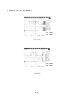
Page 22: ...2 SDRAM CLOCK FIG 2 1 3 TRAY OPEN CLOSE SIGNAL CH1 EJ CH2 EJ FIG 3 1 3 12 ...
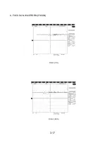
Page 27: ...8 FOCUS ON WAVEFORM FSCON FIG 8 1 CD FIG 8 2 DVD 3 17 ...
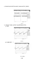
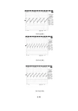
Page 29: ...FIG 10 2 480P FIG 10 3 720P FIG 10 4 1080I 3 19 ...
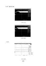
Page 30: ...11 RF WAVEFORM FIG11 1 CD FIG11 1 DVD 12 HDMI CH1 HSYN CH2 VSYN FIG12 1 480I 3 20 ...
Page 60: ...HS4 DVD_B008 VM1 0 RS232 P1 J2 1 6 5 RS232 P C BOARD TOP VIEW BOTTOM VIEW 3 64 ...
Page 62: ......


