background image

Thank you for your purchase.  The NAD VISO speakers are designed to deliver 
high performance in many uses, and we hope they add much enjoyment to your 
listening life.

For detailed information on speaker positioning, NAD VISO DVD Receiver 
set-up and complete system configuration please refer to the 
comprehensive VISO TWENTY/VISO THIRTY Owner’s Manual at 

I.   QUICK START

A. Attach the supplied adhesive backed bumpers near the corners of the LR5’s 

and C20’s bottom surface to protect the finish of speakers and furnishings.

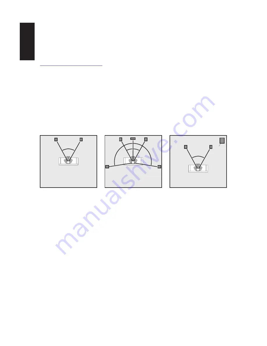
B. Position

 LR5 speakers

 as symmetrically as possible, at a comfortable 

distance from your seating position—slightly closer to each other than they 
are to you.  Position the 

C20 center channel

 directly above or underneath 

your TV screen.  (Keep its front as much in line as possible with the front of 
the picture.)  

C. Using standard lamp “zip cord” (18 gauge/1.0mm dia) wire or better, connect 

the Red (positive) binding post of each speaker to the Red terminal of your 
signal source on the channel. Similarly, connect Black (ground) on each 
speaker to Black on that channel's signal source.  (If the output of the signal 
source is via a proprietary cable with a jack at one end, connect the color-
coded wires at the other end of the cable to the speaker's similarly-coded 
posts.) 

Be sure to follow color-coding to make sure that your speakers 

are “in phase” for smoothest sound with deepest bass.

D. The loudest bass output from a subwoofer will come from corner placement. 

As you position the subwoofer outward from the corner along one wall or 
another, bass output diminishes somewhat, it also becomes more uniform 
throughout the room, with fewer of the “standing waves” that produce peaks 
and nulls at various points. Turn off all other components, and follow one of 
the connection diagrams. Connect the supplied power cord to the AC power 
socket, then plug the subwoofer into an active AC outlet. The same receptacle 
as the rest of your audio/video system or another on the same electrical 
circuit should be used to avoid ground hum. Set the subwoofer’s phase switch 
to 0° and volume switch to 0dB. Flip the Power Switch to the on position. 

www.nadelectronics.com

4

30° 30°

100°

100°

Ideal speaker placement: 5.1

60°

Ideal speaker placement: 2.1

60°

Subwoofer

One of possible 

subwoofer locations

Summary of Contents for VISO THIRTY

Page 1: ...Quick Start Guide VISO TWENTY VISO THIRTY Manuel d utilisation Manual del usuario Manuale delle istruzioni ...

Page 2: ...ratus the apparatus has been exposed to rain or moisture does not operate normally or has been dropped 14 WARNING To reduce the risk of fire or electric shock this apparatus should not be exposed to rain or moisture and objects filled with liquids such as vases should not be placed on this apparatus 15 To completely disconnect this equipment from the mains disconnect the power supply cord plug fro...

Page 3: ...Table of Contents I Quick Start 4 II Important Information on Subwoofer Level Calibration 5 III Troubleshooting 5 IV Troubleshooting Subwoofer 6 V Wiring Diagrams 8 9 VI Specifications 10 3 ENGLISH ...

Page 4: ... each speaker to Black on that channel s signal source If the output of the signal source is via a proprietary cable with a jack at one end connect the color coded wires at the other end of the cable to the speaker s similarly coded posts Be sure to follow color coding to make sure that your speakers are in phase for smoothest sound with deepest bass D The loudest bass output from a subwoofer will...

Page 5: ...calibrated subwoofer reference level is the 10dB position on the VISO subwoofer and the 10dB subwoofer level on the VISO receiver With the subwoofer volume set to 0dB if by gradually increasing bass output at the VISO receiver a point is reached at which the subwoofer starts audibly to clip and or the bass output from the subwoofer is insufficient this indicates that the volume on the subwoofer is...

Page 6: ... the subwoofer it will not power up and the front panel power indicator will remain red When using the subwoofer output of the VISO receiver no signal may be immediately present in this output The subwoofer will only power up when a signal appears at the subwoofer input If the signal cable connection is poor or has been severed the subwoofer will not power up Swap cables to determine if this is th...

Page 7: ... the Model name Serial Number date of purchase dealer name and a full description of the problem wiring appliances Replace shorten the cable connecting the subwoofer to the VISO receiver Cable runs of longer than 20 feet may require the use of a line driver not available from PSB Setting the volume switch of the subwoofer to 0dB and increasing the volume control of the VISO receiver subwoofer outp...

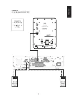
Page 8: ...ont Speaker VISO C20 Centre Speaker VISO LR5 Left Front Speaker VISO LR5 Right Rear Speaker VISO LR5 Left Rear Speaker 8 PHASE 180 0 VISO S10 Powered Subwoofer VOLUME 10db 0 db VISO S10 120V Model Only 120V 60HZ 1 6A AC FUSE T1 6AL 250V V WIRING DIAGRAMS ...

Page 9: ...2 2 1 System with VISO TWO VISO LR5 Right Front Speaker VISO LR5 Left Front Speaker 9 PHASE 180 0 VISO S10 Powered Subwoofer VOLUME 10db 0 db VISO S10 120V Model Only 120V 60HZ 1 6A AC FUSE T1 6AL 250V ENGLISH ...

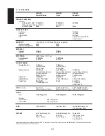
Page 10: ...propylene cone Polypropylene cone Polypropylene cone Rubber surround Rubber surround Rubber surround Crossover 3 000Hz B3 3 000Hz B3 Fixed Internal Volume 0 10 cu ft 2 8 liters 0 15 cu ft 4 3 liters 0 68 cu ft 19 3 liters Design Type Bass Reflex Sealed Bass Reflex 1 25mm Rear Port 2 64mm Down Firing Port SIZE W x H x D 5 x 8 x 7 13 3 4 x 5 1 4 x 7 9 3 8 x 14 3 4 x 15 1 2 129mm x 205mm x 178mm 350m...

Page 11: ......

Page 12: ...ATIONAL A DIVISION OF LENBROOK INDUSTRIES LIMITED All rights reserved No part of this publication may be reproduced stored or transmitted in any form without the written permission of NAD Electronics International VISO FIVE Owner s Manual Issue 2 01 08 ...

Reviews: