background image

文件编号

Doc. No.

NDT2920257

版次

Edition

2

Version 2

实施日期

Implementation date

2019-08-19

10

procedures: 

1

)用

500 Vdc

兆欧表;

(1) Use a 500 Vdc megameter

2

)在断路器处于断开状态,对进出连接板

1-2

3-4

5-6

之间,和

1

3

5

连接板(

3

个连接板

用导线相连)与外壳之间(外壳用金属箔覆盖)分别进行;

(2) Place the breaker in open status, carry out test between 1-2, 3-4 and 5-6 connection boards, 

as well as between the 1, 3 and 5 connection boards (connected with wires) and the breaker shell 
(covered by metal foil)

3

)对接至主电路的分励脱扣器,在进线与断路器外壳间;

(3) Test should be done in position between incoming wire and breaker shell to test shunt release 

in the main circuit

4

)绝缘电阻不小于

12M

Ω。

(4) Insulation resistance should not be lower than 12M

Ω

.

6.2

安装方式

Mounting method

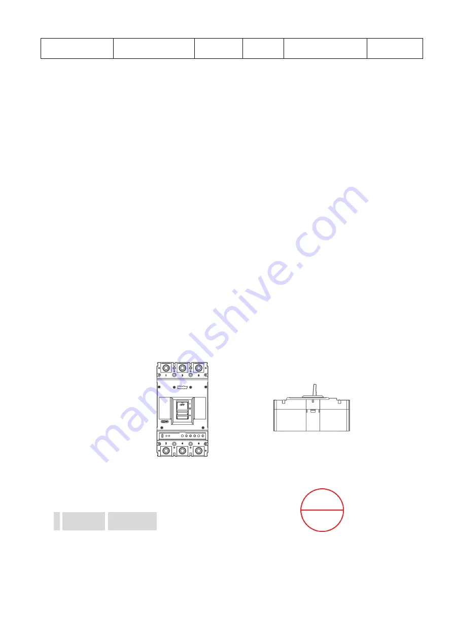
请安装在如金属等阻燃物上。断路器可垂直安装见下图

3

,也可以水平安装见下图

4

Please 

install the breaker on flame retardants such as metal, etc. It can be installed vertically is shown as 
follow Fig. 3 or horizontally is shown as follow Fig. 4.

产品垂直安装时,安装面与垂直面的倾斜角度≤

±22.5°

When the product is installed vertically, 

the angle of inclination between the installation surface and vertical surface shall be 

≤±

22.5°.

3

直安装


4

水平安装

Fig. 3 Vertical installation       

Fig. 4 Horizontal installation

7

附件说明

Accessory

7.1

分励脱扣器

Shunt release

根据引出的导线编号接入电源

,

当分励脱扣器的外加电压介于额定控制电源电压的

55%-110%

之间

时,能可靠分断断路器。

Power  supply  is  connected  to  the  shunt  release  according  to  output  wire  number,  At  rated 

2019.12.31

文件控制

Summary of Contents for NDM3EU-400

Page 1: ...ons Doc Code NDT2920257 Edition 1 Version 1 Product Model and Name NDM3EU 400 NDM3EU 400 MCCB Implementation Date 2019 08 19 Shanghai Nader Electrical Co Ltd NDM3EU 400 NDM3EU 400 Electronic MCCB Oper...

Page 2: ...19 1 Contents 2 Application Scope and Purpose 2 Description of Model 3 Technical Parameters 7 Working Environment 8 Dimensions and Installation Dimensions 9 Installation 10 Accessories 11 Operation a...

Page 3: ...and instantaneous short circuit the breaker can protect the circuit and electric power unit from being damaged 2 Description of model 1 Description of model is shown as follow Table 1 1 Table 1 Descri...

Page 4: ...and Bottom Horizontal Z2H4 Plug in Rear Connection Top Horizontal and Bottom Vertical 12 Ir A Setting current Ir A AC 250 AC 300 AC 350 AC400 AC 250 AC 300 AC 350 AC 400 13 Certification code U UL489...

Page 5: ...UPS working environment by customer Pollution class 3 Protection class IP20 Circuit breaker UL489 Certification Lug UL486E Accessories Terminal cover Double Auxiliary Contacts Shunt Trip Plug in Pre...

Page 6: ...rating Suitable combinations of current and time are adjusted by this knob so as to protect circuits and devices This operation should be done by specialized technical personnel 1 Tr Ir 2 Ir 400A Tr...

Page 7: ...lay a Ir 3 a Setting current Ir of overload long delay Allowable deviation is 3 b Tr 10 b Setting time Tr of overload long delay Accuracy of action time is 10 c I 1 15 Ir tr 2 Ir I 2 Tr c When actual...

Page 8: ...ing Environment 4 1 3 Storage condition is shown as follow Table 3 3 Table 3 Storage condition Item Specifications Ambient temperature 40 75 Relative humidity 25 95 when ambient temperature is 25 95 4...

Page 9: ...eed 50 at 40 the lowest temperature in the most humid month should not exceed 25 and the highest humidity in this month should not exceed 90 while condensation on breaker surface caused by temperature...

Page 10: ...low Table 6 6 Table 6 Installation dimensions Installation dimension Model L mm W mm H mm Y mm X mm mm Circuit breaker 277 150 123 204 48 6 Circuit breaker Plug in 357 150 155 158 70 6 2 6 Installatio...

Page 11: ...to test shunt release in the main circuit 4 12M 4 Insulation resistance should not be lower than 12M 6 2 Mounting method 3 4 Please install the breaker on flame retardants such as metal etc It can be...

Page 12: ...ram of shunt release is shown as follow Fig 5 5 Fig 5 Wiring diagram of shunt release 7 2 Auxiliary contact 7 3 Peripheral control circuits of connection of auxiliary contacts 8 Technical Data of auxi...

Page 13: ...at no short circuit or short to ground occurs between terminals of opposite polarity or exposes live parts 3 3 Check that terminal connection and fixing bolts are fastened without looseness 8 2 Commis...

Page 14: ...cludes following procedures 1 5 1 Re trip the breaker close and open the breaker use trip button to trip the breaker when it is closed repeat for 5 times to check that the breaker can reliably re trip...

Page 15: ...breaker with wet hands or electric shock would be resulted 2 2 Frequent operation will shorten service life of the breaker This product is manufactured in a sophisticated quality management system In...

Page 16: ...er can functions normally or the breaker will be replaced with a charge 10 Ordering Instruction 10 1 10 1 Customer should confirm that he or she is familiar with technical files of this product and pl...

Reviews: