background image

5

FRONT CONTROLS ANd CONNECTIONS
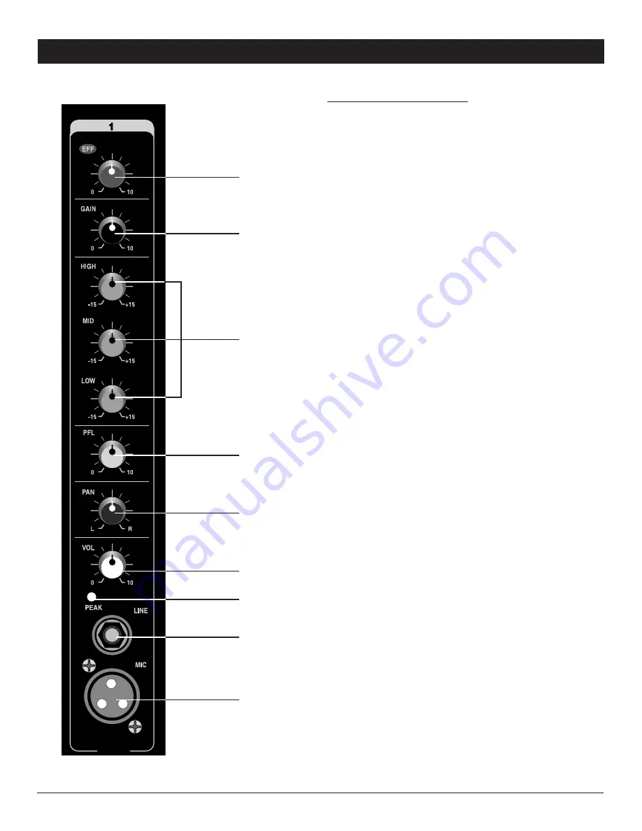
CHANNEL SECTION

(1) MIC INPUT

This electronically balanced XLR input is designed 

to accept signals from any balanced or unbalanced 

low impedance (Low Z) microphone. The XLR jack is 

configured for: Pin1 = ground, Pin2 = positive (+), Pin3 = 

negative (-).

(2) LINE INPUT

This 1/4” input is designed to accept balanced or 

unbalanced line-level signals such as those from 

keyboards, drum machines, or samplers. If a balanced 

signal is to be connected to the line input, then a 1/4” TRS 

(stereo) phone plug should be wired for:  Tip = positive (+), 

Ring = negative (-), Sleeve = ground.

(Note: Only the Mic or the Line input of a given channel 

should be connected at one time.  Do not connect both at 

the same time.)

(3) PEAK LEd INdICATOR

The PEAK LED illuminates when a channel input 

is overloading.  It detects the peak level after the 

EQUALIZER CONTROLS (5)

 and will light just before 

clipping to warn that the signal is approaching overload. 

You do not want the Peak LED to light except very 

intermittently. If it lights persistently, reduce the 

GAIN 

CONTROL (4)

.

(4) GAIN CONTROL

The GAIN control adjusts the input sensitivity of the mic 

and line inputs on each channel. This control can be 

adjusted to accommodate input signals from a wide variety 

of sources, from the high outputs of keyboards or drum 

machines to the small signal outputs of microphones. The 

best balance of S/N and dynamic range will be achieved 

if you adjust the GAIN control on each channel separately 

so that the maximum signal level can be input without 

distortion. While speaking, singing, or playing an instrument 

at maximum performance level, increase the GAIN control 

until the 

PEAK LEd (3)

 flashes, then turn down the GAIN 

control until the flashing stops.

(5) EQUALIZER CONTROLS

All input channels are fitted with a three-band EQ - HIGH, 

MID, and LOW. All three bands have up to 15 dB of cut 

and boost, with a center detent for OFF. The frequency 

response is flat when all three EQ knobs are in the center 

detent position. The HIGH and LOW shelving controls have 

their frequencies fixed at 12 KHz and 90Hz respectively. 

The MID control has a peaking response at 2KHz. The 

channel EQ is a valuable feature of the mixer as it allows 

the user to control the tonal characteristics of each channel 

separately. For example, boosting the LOW can fatten the 

(1)

(2)

(3)

(9)

(8)

(6)

(5)

(4)

(7)

Summary of Contents for SPM-4250

Page 1: ...SPM 4250 P O W E R E D M I X E R 4 Channel Stereo Powered Mixer O W N E R S M A N U A L...

Page 2: ..._ _____________________ Zip______________________ Model _____________________________________________ Serial _ ____________________________________________ FEATURES TABLE OF CONTENTS FEATURES 2 WARNIN...

Page 3: ...he ears you should consult an audiologist 5 The product should be positioned so that proper ventilation is maintained 6 The product should be located away from heat sources such as radiators heat vent...

Page 4: ...r cooling Also do not place the SPM 4250 on high temperature devices such as power amplifiers etc or the unit may overheat in operation Although the unit s chassis is shielded against radio frequency...

Page 5: ...The GAIN control adjusts the input sensitivity of the mic and line inputs on each channel This control can be adjusted to accommodate input signals from a wide variety of sources from the high outputs...

Page 6: ...pre fader listen control adjusts the volume of the mono signal sent to the HEADPHONES 22 provided the master section PFL SWITCH 23 is enabled The signal is post EQ 5 and independent of the channel VOL...

Page 7: ...s in the master mix The red PEAK LED will light when the output signal is just below clipping It is acceptable if the red LED lights occasionally If the red LED lights more than occasionally you shoul...

Page 8: ...NECTOR The IEC socket is used to connect the power cord to an AC power source Caution Do not remove the center grounding pin 28 FUSE COMPARTMENT Replace with only the same type fuse as listed in the S...

Page 9: ...TRS phone jacks for balanced unbalanced stereo or in out inserts 3 1 4 TS unbalanced 4 RCA pin unbalanced Figures 1 Balanced XLR input connections 2 Stereo headphone connection with 1 4 TRS plug 3 1 4...

Page 10: ...OWER OUT 8 BOTH CHANNELS DRIVEN 105W RMS per side 4 BOTH CHANNELS DRIVEN 125W RMS per side FREQUENCY RESPONSE 10Hz 20KHz 3dB 5 GENERAL POWER REQUIREMENTS Voltage selectable 115VAC 60Hz or 230VAC 50Hz...

Page 11: ...artment Any service not performed by Nady will automatically void this warranty 2 Items not covered physical damage resulting from improper handling of the unit in transit from the factory by the ship...

Page 12: ...or money order or pay by credit card per instructions by the Nady Service Department Ship your unit prepaid to Nady Systems Service Department 6701 Shellmound Street Emeryville CA 94608 Include a brie...

Reviews: