


22
(Optional)
14
20
15
15
16
16
19
ANT-B
POWER
DC13~15V
500mA
MUTE 2
MIN MAX
SUM OUT
MIXED MIC-1 + MIC-B
UNBALANCED
MIC-2 OUT
BALANCED
MIC-1 OUT
BALANCED
ANT-A
MUTE 1
MIN MAX
17
17
18
21
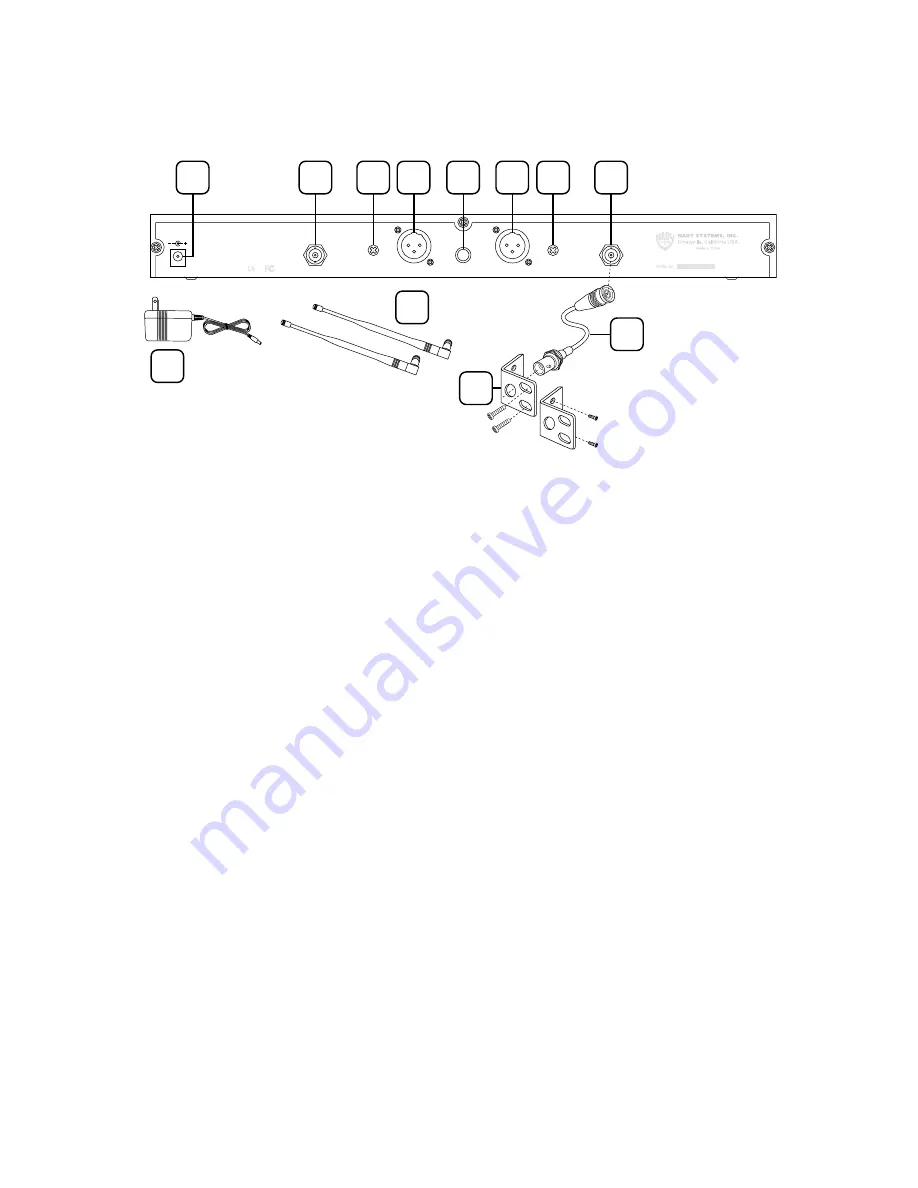
2W-1KU Receiver: Back View
5
14. DC INPUT JACK
For using supplied external
AC/DC adapter to power the receivers
15. RF CONNECTORS
A/B Antenna jacks for RF
True Diversity reception
16. MUTE (SQUELCH) CONTROL
Controls the mute
level for each receiver—turn CW for maximum
range; turn CCW for minimum range, if
needed, to minimize noises from outside
RF interference upon muting
17. BALANCED MIC OUT
Audio output connection
for each receiver—fixed mic level, not
adjustable
18. UNBALANCED AUDIO OUT
SUM Volume Level
audio output for both receivers—adjustable
LINE level
19. DC POWER SUPPLY UNIT
DC16VDC/800mA
connects to
DC Input Jack (14)
20. ANTENNAS
½ wave antennas connect to
A/B antenna jacks
21. RACK EARS
Attached to both sides of receiver
and the equipment racks with screws
22. ANTENNA EXTENSION CABLES (Optional)
Attach coax cables with BNC connectors from
back antenna jacks to rack ear holes for front
antenna mounting configuration


