


8
opeRaTIon
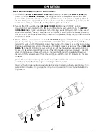
WGT Instrument Bodypack Transmitter
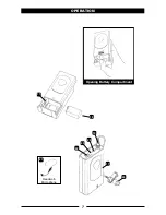
1. Snap open the
BATTERY COMPARTMENT (25)
and insert a fresh
9V BATTERY (26)
, observing the correct
polarity. Close the compartment. The WGT-15 is provided with a 3.5 mm
LOCKING JACK (27)
for
connecting the
INSTRUMENT CABLE (28)
. To secure the connection, turn the metal slip ring on the
plug clockwise to thread it on to the jack. To unplug, reverse the process. Slip the transmitter
into a pocket or clip on to your clothes or instrument strap.
[Note: As the cord to the instrument also serves as the antenna, be sure to extend it fully for
maximum range. Rolling up or shortening the cord may reduce the effective operating range.]
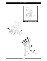
2. Turn on the WGT by sliding the
OFF/STANDBY/ON SWITCH (29)
to the STANDBY position (transmitter
on, audio muted) or the ON position (transmitter and audio both on). The
BATTERY INDICATOR LED
(30)
will give a single quick flash, indicating usable battery strength. In the case of a dead or low
battery, the LED either will not go on at all or will stay on continuously, indicating that the battery
should be replaced with a fresh one.
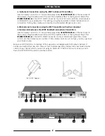
3. The WGT transmitter is now ready to use. The
TX DISPLAY LEDs (7)
on the 401X QUAD receiver
should now be lit, indicating a received signal from the transmitter. Adjust the volume of the
receiver as per the Audio Output Instrument Connections section of the above 401X QUAD
receiver instructions. The
AF LEVEL LED DISPLAY (7)
on the 401X QUAD receiver will light up as if
the input signals are getting stronger. Occasional flickering on and off during use of the LED
indicator is normal. However, if the LED stays on continuously, turn down the instrument volume
control or noticeable distortion may result. For ultra high-gain instrument sources such as active
bass pickups or even extra hot guitar pickups, an attenuation pad may be required to eliminate
unwanted distortion.
[Note: The
INPUT LEVEL CONTROL (31)
is not operable because it is preset and switched internally
at the factory to instrument GT input mode. The control is only used for Headworn Mic (HM)
and Lavalier (LT) input modes.]
[Note: Scratchy noises can sometimes occur when some electric guitars/basses with dirty pots
or connections are used with any wireless system. For this reason, the supplied
INSTRUMENT
CORD (28)
has a factory installed capacitor inside the
¼
” plug. This capacitor provides first order
filtering of the RF signal from the cord into the guitar and eliminates virtually all scratchy noises.
Should your equipment still produce scratchy noises, we suggest these steps to eliminate them:
1) Make sure all guitar volume and tone pots are clean and all contacts are solid—
this is very important.
2) Provide extra filtering with a 220 pF capacitor soldered across the hot to ground terminals
of the guitar’s volume and tone pots.)


