
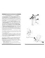
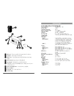
XR-61 Receiver
1
6
8
9
4
13
1
6
11
3
12 10 7
2
5
5
7
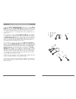
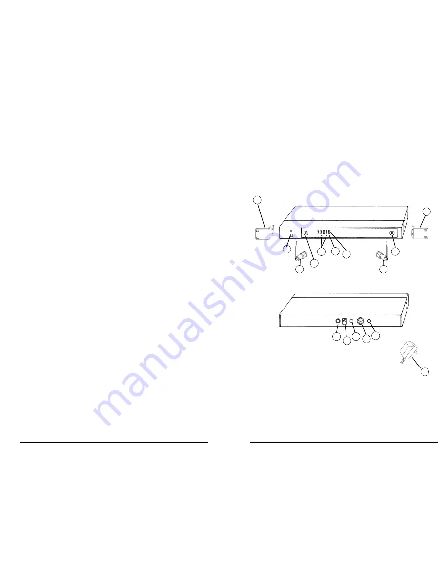
5. Connecting the Audio Output
The XR-61 receiver provides both a fixed mic level
BALANCED AUDIO OUTPUT XLR (10)
and an adjustable line level
UNBALANCED AUDIO OUTPUT 1/4” JACK (11)
. The level
from the
UNBALANCED OUTPUT
is controlled by the rear panel
VOLUME CONTROL (12
).
(Note: As when making any connection, make sure the amplifier or mixing board volume is
at the minimum level before plugging in the receiver to avoid possible sound system dam-
age. Also make sure that the phantom power on the input of the mixer is turned OFF
before making connection to the receiver.)
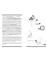
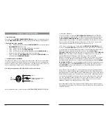
a. Instrument Connection (using the WGT-15 instrument transmitter)
Insert an audio cord with a 1/4” mono phone plug in the
UNBALANCED OUTPUT
JACK (11)
on the rear panel of the receiver. Plug the other end of the cord into an
amplifier, effects, or mixing board. Adjust the
VOLUME CONTROL (12)
on the XR-61
receiver clockwise to about 3/4 rotation, until the volume level is comfortable for your
application. This setting is roughly equivalent to a direct instrument cord connection.
Turning the volume up to maximum will provide 4dB gain over a cord.
b. Microphone Connection (using the WLT-15 transmitter with either a headset or
lavalier microphone or the WHT-15 handheld microphone transmitter)
For microphone use, either the
BALANCED MIC AUDIO OUTPUT XLR (10)
or the 1/4”
line level
UNBALANCED OUTPUT (11)
can be used. The XLR output is set at a non-
adjustable microphone level, similar to hardwired mic levels. Plug an XLR
connector into the XLR output jack on the rear of the unit and plug the other end
into your amplifier or mixing board. (Note: Make sure the phantom power on your
mixing board is turned off and the volume is turned down when making connections.)
For your convenience, the XLR output level is preset at the factory and is not adjustable
with the receiver volume control. To use the
1/4” UNBALANCED OUTPUT JACK (11)
,
follow the instructions for the
Instrument Connection
(above), except start with the
receiver volume at 1/2 MAX and adjust the volume control until the volume level is
optimal. If the volume control is set too high, you may overload your mixer or amp.
6