
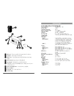

25
22
24
29
28
27
22
23
26
11
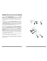
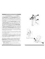
Opening Battery Compartment
1. Snap open the
BATTERY COMPARTMENT (22)
and insert a fresh
9V BATTERY (23)
,
observing the correct polarity. Close the compartment.
2. The WLT-15 is provided with a
3.5 mm LOCKING JACK (24)
for connecting the micro-
phone. Plug in either the
LAVALIER/LAPEL (25)
or the
HEADWORN MICROPHONE (26)
, as
supplied. To secure the connection, turn the metal slip ring on the plug clockwise to thread
it on to the jack. To unplug, reverse the process. Slip the transmitter into a pocket or clip
on to your clothes. To use the lavalier mic, attach it at chest level. Do not place too close
to the mouth-a distance of about six inches usually works best. To use the headworn mic,
place it on the head and adjust the mic boom so that the mic is about one inch to the side
of the front of the mouth. (Note: The lavalier or headworn mic wire is also the transmit
antenna, and rolling up or shortening the wire may reduce the effective operating range.
Extend the wire fully during use, and keep it as straight as possible.)
3. Turn on the WLT-15 by sliding the
OFF/STANDBY/ON SWITCH (27)
to the STANDBY
position (transmitter on, audio muted) or the ON position (transmitter and audio both on).
The
BATTERY INDICATOR LED (28)
will give a single quick flash, indicating usable battery
strength. In the case of a dead or low battery, the LED either will not go on at all or will
stay on continuously, indicating that the battery should be replaced with a fresh one.
4. The microphone is now ready to use. The
A
and/or
B DIVERSITY LED INDICATORS (8
)
and most or all of the
RF DISPLAY LEDs (9)
on the XR-61 receiver should now be lit, indicat-
ing a received signal from the transmitter. When ready to speak, slide the transmitter switch
to the ON position and adjust the volume of the receiver as per the
Audio Output
Microphone Connection
section of the above XR-61 receiver instructions. The
AF LEVEL
LED DISPLAY (13)
on the XR-61 receiver will light up to 5 LEDs (4 green and 1 red) for all
input signals. Occasional flickering on and off during use of the top red LED indicator in
this display is normal, however if the red LED stays on continuously, it means the signal is
too loud and there is the possibility of overload distortion. Re-position the microphone far-
ther from the source or adjust the
AUDIO INPUT LEVEL CONTROL (29)
until the red LED
indicator flickers only on the loudest inputs.
[Note: Observe care in selecting P.A. volume, transmitter location and speaker placement
so that acoustic feedback (howling and screeching) will be avoided. Please also observe
the pickup patterns of the microphone selected: omnidirectional mics pick up sound equally
from all directions and are prone to feedback if not used carefully. Unidirectional mics are
more resistant to feedback, but pick up sound sources best that are directly in front of the
mic. Also, mics that are farther from the sound source, such as lavaliers, require more
acoustic gain and thus are also more prone to feedback than close-source mics such as
handheld or headworn mics that are used close to the mouth.]
(Note: Microphone elements can easily be destroyed by the buildup of salts and minerals
from perspiration and saliva. It is good practice to put a windscreen on the mic element at
all times to protect it.)
10
WLT-15 LAVALIER/LAPEL OR HEADWORN MICROPHONE BODYPACK TRANSMITTER