background image


19 

TY-EJ15-003A Rev.2 


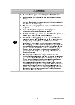
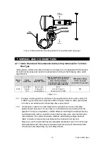
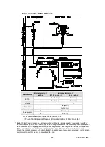
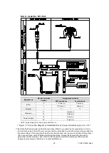
7.1.8  Connect the cable with crimp terminal to the terminal block. 


7.1.9 


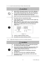
Tighten the terminal box cover firmly to seal the terminal box.   


Never perform wiring with moisture on the product. Moisture or 
other foreign matter entering the case may cause malfunction. 


Do not perform wiring when the power is turned on. Otherwise 
damage to the product and electric shock may result. 


Never loosen any screws other than those on the terminal block. 


Be careful not to lose any parts when wiring. 


Tighten the M3.5 screws of the terminal block with a tightening 
torque of 0.8 to 1.0 N·m. 


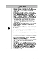
When using a bare crimp terminal, keep a necessary insulation 
distance with an insulation tube or others to prevent a live part 
exposure for possible electric shock or short circuit (see 
"Figure 7-3"). 


Connect so that the polarity is correct. 


Be careful not to short-circuit the terminals. 


The protection rating of this product is guaranteed only when 
the components are properly assembled. 


Ensure that the O-ring is tightly fitted to the seal surface of the 
inner case (see "Figure 7-2"). Also check that there are no 
scratches, breaks or dirt on the O-ring. 


Tighten the O-ring so that it is not twisted over the entire 
circumference. 


Be careful not to get the wires caught when tightening. 


Be careful not to scratch the seat surface of the inner case 
(terminal box cover). 

CAUTION 

CAUTION 

< Figure 7-3 > 

Insulation tube 

Insulation distance 

Live part 

Summary of Contents for EJ15

Page 1: ...User s Manual EJ15 Intrinsically Safe Pressure Sensor for High Pressure Hydrogen Application EJ15 H 7 2 ...

Page 2: ...Terms Safety precautions in this manual are classified according to the following definitions Indicates the risk that users may suffer from damage including death or serious injury and extremely high urgency at the time of occurrence of risk Indicates the risk that users may suffer from damage including death or serious injury Indicates the risk that users may suffer from minor injury and the risk...

Page 3: ...ds such as rain may be splashed 2 Where atmosphere contains moisture salt or sulfur 2 2 Wiring that impairs the explosion proof performance of Intrinsically Safe Circuits 3 3 Maintenance and inspection of the product in a Hazardous Area 4 Do not use this product on measuring fluid which are corrosive to fluid or gas contacting areas Do not use this product if failure or malfunction of the product ...

Page 4: ...ses injury or damage to the surrounding environment Install the product in accordance with the installation instructions in the User s Manual For repair please contact us Disassembly or modification of the product on your own may cause failures These precautions are selected from our common safety precautions for all products that correspond to the EJ15 pressure sensor EJ15 specific precautions ar...

Page 5: ...g Direction 13 6 3 Safety Barrier 14 6 4 Cable 14 6 5 Precautions for Possible Water Spraying to Pressure Sensor 14 7 WIRING AND CONNECTION 15 7 1 Cable Gland and Transmission Cable Crimp Terminal 15 7 2 Transmission Cable with M12 Connector 20 7 3 System Configuration Diagram 23 7 4 Wiring Example 23 7 5 Intrinsically Safe Equipment and Safety Barrier 29 7 6 Wiring of Intrinsically Safe Equipment...

Page 6: ...here almost all types of Explosive Gas exist It has excellent hydrogen resistant characteristics with the use of SUH660 A286 for diaphragms and SUS316 Ni equivalent amount for fittings 2 2 Operating Principle The product has an intrinsically safe construction and is installed mainly in the Hazardous Area such as a high pressure hydrogen station The output is 4 to 20mA DC through a safety barrier w...

Page 7: ... 50 deg C Operating temperature humidity range 20 to 60 deg C 35 to 85 RH no freezing or condensation Storage temperature humidity range 30 to 80 deg C 35 to 85 RH no freezing or condensation Insulation resistance 100 MΩ or more 50V DC collectively for fitting to input output terminal CE marking Compliance directive 2014 30 EU EMC Directive Compliance standards EN61326 1 2013 EN61326 2 3 2013 Conn...

Page 8: ...02IJ Identification No GYJ19 1315 19 AV4BO 0654 Hazardous Area Zone 0 Category 1G Zone 0 Zone 0 Zone 0 Zone 0 Compliance standards IEC60079 0 2017 IEC60079 11 2011 EN60079 0 2018 EN60079 11 2012 JNIOSH TR 46 1 2015 JNIOSH TR 46 6 2015 CNS3376 0 CNS3376 11 GB3836 1 2010 GB3836 4 2010 GB3836 20 2010 IEC60079 0 2017 IEC60079 11 2011 Notification No 2019 15 Compliance directive 2014 34 EU ATEX Directi...

Page 9: ...0 mH Maximum external capacitance Co 0 093 μF 0 083 μF 0 100 μF Ambient temperature 60 degrees C 60 degrees C 70 degrees C Load resistance in safe area 800Ω MAX 20 mA DC 450Ω MAX 20 mA DC 550Ω MAX 20 mA DC Safety barrier can be selected by the user 3 2 3 Zener barrier Non hazardous Area The following table shows a recommended Zener barriers safety barrier to be used with the EJ15 pressure sensor M...

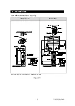
Page 10: ...10 TY EJ15 003A Rev 2 4 DIMENSIONS 4 1 External Dimensions Typical M12 Connector Terminal Box SUS316L fitting will be printed as LC on the hexagon part Figure 4 1 ...

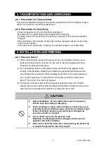
Page 11: ...e pressure line with liquid in the pipeline Since liquid is incompressible tightening the thread may generate high pressure and may damage the instrument When installing the product in the existing pressure line or when replacing it remove fluid from the piping connection side leave about 15 to 20 mm of air before screwing it 3 Though this instrument has an IP65 equivalent protection class JIS C 0...

Page 12: ... the outer terminal box In the event that the grounding is unavailable from the piping installation EJ15 body obtain it by using EJ15 earth terminal shielded cable wire for M12 connector type and ground terminal of the terminal block for terminal box type However when both the EJ15 body and earth terminal are grounded provide single point grounding so that there is no potential difference If the t...

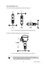
Page 13: ...ox type Mount the terminal box type with the terminal box facing up as shown in Figure 6 2 When mounting the product sideways make sure that the terminal port faces downward Fig 6 1 Recommended mounting direction for M12 connector type Figure 6 2 Recommended mounting direction for terminal box type Terminal port Top Bottom Bottom Bottom Top Bottom Top Top ...

Page 14: ...l box type where a heavy stainless steel terminal box may be damaged by excessive vibration or shock Never pull the cable or bend it extremely Also during wiring be careful not to subject the product to the cable weight Atmospheric pressure is transmitted to the gauge by way of a cable When the cable is compressed midway due to extreme bending or use of clamp or bushing or when the cable is long i...

Page 15: ...ameter matching the cable gland size and the lead wire with a conductor cross sectional area core wire matching the crimp terminal The cable should also matches withstanding voltage between cable conductors core wires and between the conductor and ground Moreover use the cable that has less allowable parameters see 3 2 Intrinsically Safe Specifications than those provided as external wiring of Int...

Page 16: ...nal for M3 5 3 Attach the crimp terminal to the end of the and lead wires If the shielded wire 1 is required attach the crimp terminal also to the end of the shielded wire Be sure to cover the shielded wire with an insulating tube to prevent short circuit 4 Adjust the size of the crimp terminal before mounting so as to obtain a recommended dimension of 60 mm after mounting 5 Use R1 25 3 5 or equiv...

Page 17: ... equivalence to IPX5 is guaranteed only when the respective parts are correctly installed Use a special tool to peel off the cover and prevent damage to the cable core The crimp terminal to be attached to the lead wire must be a suitable one round type Do not connect Y shaped terminals that easily come off or bare wires that easily stick out The screw size of the terminal block to which the crimp ...

Page 18: ...the cable gland securely to prevent water from entering as it will affect the waterproof performance When tightening the body nut of the cable gland hook a wrench on the width across a flat section of the cable outlet so that no excessive force is applied to the cable outlet The protection rating of this product is guaranteed only when the components are properly assembled Tighten the seal nut sec...

Page 19: ...crimp terminal keep a necessary insulation distance with an insulation tube or others to prevent a live part exposure for possible electric shock or short circuit see Figure 7 3 Connect so that the polarity is correct Be careful not to short circuit the terminals The protection rating of this product is guaranteed only when the components are properly assembled Ensure that the O ring is tightly fi...

Page 20: ...able not exceeding the allowable parameters defined for external wiring of the Intrinsically Safe Circuits refer to 3 2 Intrinsically Safe Specifications will vary depending on your safety barrier Li Lc Lo Lc Inductance of external transmission cable Li Maximum internal inductance of EJ15 Intrinsically Safe Circuit 0mH Lo Maximum external inductance of Intrinsically Safe Circuit for safety barrier...

Page 21: ... terminal arrangement to perform wire connection Insert the M12 connector on the cable side into the connector groove on the main body side Tighten the nut by hand until it does not move Tightening torque 0 4 to 0 5 N m Connector terminal arrangement Terminal number 2 wire system Cabling color For our optional cable 1 Power Brown 2 White 3 Power Blue 4 Black Please note that you will not use the w...

Page 22: ...of the terminal block for terminal box type However when both the EJ15 body and earth terminal are grounded provide single point grounding so that there is no potential difference Check the specifications of this product before installation to determine the rated value of the power supply to use Ensure that the internal resistance of the external device is within the rated operating range of the l...

Page 23: ...ing 7 4 1 Insulated barrier Install the intrinsically safe device EJ15 in the Hazardous Area and the safety barrier insulated barrier and general equipment power supply and receiver in the Non hazardous Area as shown in the connection diagram on and after the next page When you purchase an insulated barrier a single Class A grounding under the intrinsically safe regulations is not required For wir...

Page 24: ...s grounded as it is required to do so For the terminal box type the EJ15 main body can also be grounded from the M4 screw portion provided on the outer surface If the piping EJ15 unit cannot be grounded use the ground terminal of this product M12 connector type cable shielded wire terminal box type terminal block grounding terminal to ground the product However when both the EJ15 body and earth te...

Page 25: ...ded use the ground terminal of this product M12 connector type cable shielded wire terminal box type terminal block grounding terminal to ground the product However when both the EJ15 body and earth terminal are grounded provide single point grounding so that there is no potential difference Equipment Barrier terminal number Equipment terminal M12 connector Terminal box EJ15 2 1 Power Power 1 3 Po...

Page 26: ...nded as it is required to do so For the terminal box type the EJ15 main body can also be grounded from the M4 screw portion provided on the outer surface If the piping EJ15 unit cannot be grounded use the ground terminal of this product M12 connector type cable shielded wire terminal box type terminal block grounding terminal to ground the product However when both the EJ15 body and earth terminal...

Page 27: ...so that the main body fitting is grounded as it is required to do so For the terminal box type the EJ15 main body can also be grounded from the M4 screw portion provided on the outer surface If the piping EJ15 unit cannot be grounded use the ground terminal of this product M12 connector type cable shielded wire terminal box type terminal block grounding terminal to ground the product However when ...

Page 28: ... 35 mm wide DIN rail is required For wiring and other details refer to the instruction manual of the purchased product Barrier model No MTL7787 Equipment Barrier terminal number Equipment terminal M12 connector Terminal box EJ15 3 1 Power Power 4 3 Power Power Ground Ground terminal 1 1 Receiver 2 Output Ground terminal Output Power supply 1 Power Ground terminal Power NOTE Suitable diameter of ba...

Page 29: ...ombination condition Safety barrier safety holding rating Maximum input voltage Ui Maximum output voltage Uo Maximum input current li Maximum output current lo Maximum input power Pi Maximum output power Po Parameter Combination Conditions Parameters for EJ15 and wiring Combination condition Safety barrier parameter Maximum internal inductance Li Wiring inductance Lc Maximum external inductance Lo...

Page 30: ... zero point adjustment and starting a production run For intrinsically safe wiring follow the guideline User s Guide for Factory Explosion proof Equipment Gas Explosion proof 2012 issued by the Occupational Safety and Health Research Institute Avoid applying pressure exceeding the rated pressure indicated on the product label Do not perform wiring or insert connectors while the power is on Otherwi...

Page 31: ...ise Keep the product away from the wiring carrying high current Ground the product so that the specified ground point is electrically grounded see Fig 7 3 7 4 and 7 5 Keep the product away from electrically charged machines or objects Conductive noise Use the stable power supply that is difficult to generate noise Install power supply or output measurement equipment in an environment that is imper...

Page 32: ...MΩ or more at 50V DC 6 Leakage check and thread re tightening 7 Waterproof check and fastening of the cable gland terminal box and the like Only an appearance check is allowed in a hazardous area All other maintenance work must be performed in the Non hazardous Area and never in the Hazardous Area Avoid electrostatic charge When cleaning the exterior use a soft damp cloth Do not use thinner or ben...

Page 33: ... note describing the details of the damage Never remove the zeroing screw and surrounding parts rubber cover from the case Be careful not to apply excessive load The protection of the IP65 may be impaired Be careful not to apply excessive force to the zeroing screw 5N within 10 seconds Otherwise damage to the zeroing screw and circuit parts can result Use the cross slot driver bit No 0 and do not ...

Page 34: ... forces beyond control Secondary damage is generated from incompatibility of the product including the above conditions Note that traces of deformation wear and burnout of parts are apparently found regardless of recognition of your incorrect handling the product is out of the warranty range and is repaired or replaced for pay 12 2 Export Administration Regulations To export the product check Fore...

Page 35: ... MEMO ...

Page 36: ...r manual Unauthorized reproduction or reproduction is strictly prohibited For other questions contact our sales office nearest you or call the number below USER S MANUAL EJ15 Intrinsically Safe Pressure Sensor for High Pressure Hydrogen Application EJ15 H January 2020 Rev 2 Website http www naganokeiki co jp lng eng NAGANO KEIKI CO LTD Head office 1 30 4 Higashi magome Ota ku Tokyo 143 8544 Phone ...

Reviews: