background image


TY-GC62-010A Rev.2 

Items 

Descriptions 

Display range 

-10 to 110 %F.S. of pressure range,     

-1999 to 6000 while display scaling 

Max. allowable 

pressure 

50 kPa (100 kPa for 10 kPa or higher) 

Pressure 

resistance 

200 kPa 

Measured object 

Dry air, nitrogen (no moisture or dust should be contained) 

Operating 

conditions 

In a normal condition, where there are no flammable gases or 

liquids that cause ignition and explosion 

Connection 

G1/8 

Gas contact 

material 

Silicon, aluminum, silicone, glass, ABS 

Display method 

4 digit LED digital display (character height: 10 mm) 

Display interval 

200 ms 

Power supply 

12 to 24V DC +/-10% (4 to 20mA output: 15 to 24V DC +/-10%) 

Ripple voltage 10% (P-P) or lower 

Consumption 

current 

55 mA or less (4 to 20mA output: 75mA or less) 

Output 

Comparator output 

Output method: 2 relay contact output   

(110V AC, 0.2A resistance load) 

Response speed: 5 ms or less (GC62-

□□

2: 10 ms or less) 

Dead band: Variable (hysteresis Mode); 

1%F.S. fixed (window comparator) 

Delay: 0 to 2.00 s (ON/OFF) 

Operation lamp: red LED (OUT 1, 2) lamp is lit when it is ON 

Analog output: 4 to 20mA DC (source) or 1 to 5V DC 

Response speed: 50 ms or less (no filter) 

Load resistance: 

400 Ω

 max. (4 to 20mA DC output) 


10 kΩ

 min. (1 to 5V DC output) 

Functions 

Extraction of square root (optional): to display wind speed & volume 

Scaling: display value, analog output 

Loop check: Comparator output, analog output 

Filter: None, 25 ms, 250 ms, 2.5 s, 5 s, 10 s (time-constant) 

*The set value is reflected in the comparator output & analog output. 

Error: excessive voltage, outside pressure range during zero 

adjustment 

Hold: to display peak value and bottom value 

Miscellaneous: one-touch zero adjustment, key lock 

Protection circuit 

Reverse connection of power supply 

Warm-up period 

15 minutes or longer (30 minutes is recommended) 

Operating 

temperature limits 

10 to 50°C (no condensation & freezing) 


Summary of Contents for GC62 Series

Page 1: ...1 TY GC62 010A Rev 2 GC62 Digital Differential Pressure Gauge User Manual 7 1 ...

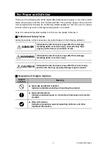
Page 2: ...sed on the following definition Indicates the risk that users may suffer from damage including death or serious injury and extremely high urgency at the time of occurrence of risk Indicates the risk that users may suffer from damage including death or serious injury Indicates the risk that users may suffer from minor injury and the risk that only property damage may be caused Description of Graphi...

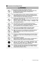
Page 3: ...roduct in dangerous places with combustible gas or liquid which may cause ignition or explosion Do not use non designated batteries and power supply Use of them causes failures fires or electric shocks Make sure that dust or misty fluid does not enter the pressure element which may cause inaccurate measurements or product failure If failures or malfunctions of this product may threaten human life ...

Page 4: ...o the installation procedure described in the user manual Operate switches accurately according to the user manual Incorrect operation of them may cause malfunctions Contact us for repair Disassembly or modification of the product on your own may cause failures ...

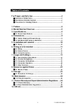
Page 5: ... removal 10 5 1 Piping 10 6 Wiring and Connection 11 6 1 Wiring 11 6 2 Internal Format 12 6 3 Contact Protection 12 7 Usage and Settings 13 7 1 How to Switch to Each Mode 13 7 2 Function Setting Mode 15 7 3 Comparator Setting Mode 18 7 4 Comparator Operation 20 7 5 Other Functions 21 8 Measures against Noise 23 8 1 Effects of Noise 23 9 Storage 23 9 1 Precautions for Storage 23 10 Maintenance 24 1...

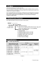
Page 6: ...ng related facilities 2 Model Number Structure This chapter describes the structure of product model number 3 Specifications 3 1 Product Specifications Differential pressure range maximum pressure display Accuracy Temperature coefficient Pressure display Analog output 0 to 50Pa 50 0 50Pa 50 0 1 5 F S 1digit 1 5 F S 0 1 F S C Zero Span 0 to 100Pa 100 0 100Pa 100 0 0 to 200Pa 200 0 200Pa 200 0 to 0 ...

Page 7: ... 0 2A resistance load Response speed 5 ms or less GC62 2 10 ms or less Dead band Variable hysteresis Mode 1 F S fixed window comparator Delay 0 to 2 00 s ON OFF Operation lamp red LED OUT 1 2 lamp is lit when it is ON Analog output 4 to 20mA DC source or 1 to 5V DC Response speed 50 ms or less no filter Load resistance 400 Ω max 4 to 20mA DC output 10 kΩ min 1 to 5V DC output Functions Extraction ...

Page 8: ...s 1 Case structure Indoor use equivalent to IP40 Case material PC ABS UL 94 V 0 Weight Approx 95 g panel mount approx 140 g wall mount Accessory Panel adapter for panel mount Hexagon socket head plug for panel mount Unit seal for extraction of square root function 1 This product cannot be used for strictly measuring the leakage such as in a leak test etc Table3 2 ...

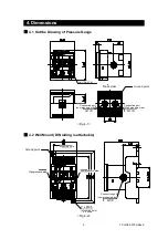
Page 9: ...unt DIN railing is attachable Mounting hole Low pressure side High pressure side Mounting hole Connection port Low pressure side G1 8 2 x Ø4 5 Fig 4 1 Unit Pa kPa Connection port Low pressure side Connection port High pressure side G1 8 G1 8 Rear view Fig 5 2 Ground point Ground point ...

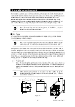
Page 10: ...o the connection port H and the low pressure side to the connection port L The pressure connection ports of the panel mount model are located on the rear side L and H 1 each and on the side L and H 1 each Use the connection port of L and H to be used and fill in the other unused ports other L and H using the hexagon socket head plug all way up to the main body When the plug is used repeatedly wrap...

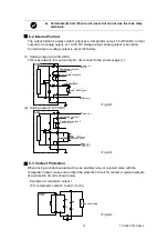
Page 11: ...stallation 6 Wiring and Connection 6 1 Wiring Follow the figures to perform wiring Use M3 terminal screw Always use a crimp terminal JIS C2805 Type R 1 25 3 or equivalent for wiring In that case tightening torque to the terminal screw should be 0 5 N m or less CAUTION Be careful not to cause an excessive impact on the product such as hitting or dropping during installation of piping Secure a space...

Page 12: ...r source only Do not connect to the power supply 2 Analog output 1 to 5V DC 6 3 Contact Protection When driving an inductive load such as an auxiliary relay or solenoid valve with the comparator output make sure to insert the protection circuit for contact A typical example of a protection circuit is shown below Example of comparator output 1 For comparator output 2 read 1 to 2 Fig 6 2 Fig 6 3 Fig...

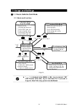
Page 13: ...an 3 sec 3 sec or longer Less than 3 sec 3 sec or longer Power ON End Comparator Setting Loop Check Mode Manual testing of the pressure display comparator output and analog output regardless of the applied pressure Function Setting Mode Measurement Mode Zero Adjustment Mode Hysteresis setting Set the dead band set point Set the ON OFF delay time Window comparator setting Set the output setting ran...

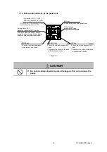
Page 14: ...ードではボトムホールド値 測定モードではピークホールド値 を表示します を表示します Comparator OUT1 OUT2 Operation indication LED red ADJ key To use during zero point adjustment LED to display pressure set value Setting Mode SET Operation indication LED orange LED lights up during setting flashes during loop check peak bottom display and turns off during other operations MODE key DOWN key To switch from each operation mode to each sub mo...

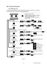
Page 15: ... Setting Mode Select comparator operation Select display with output options Display scaling Decimal point position Display scaling When etc display scaling is selected 3 sec or more Analog scaling Analog scaling 3 sec or more Pressure at analog output zero point Display scaling Window comparator Display value at the lowest pressure range Display value at the highest pressure range Filter setting ...

Page 16: ...es to be displayed on LED display is scaled to an arbitrary value against the applied pressure This function scales the LED display value to the minimum maximum value of the pressure range and does not affect the relationship between applied pressure and analog output Use key to change to Display Scaling After is displayed for one second the decimal point in the current Measurement Mode appears Us...

Page 17: ...og output with output options This mode sets the pressure corresponding to the analog output zero point 4mA DC or 1V DC span point 20mA DC or 5V DC Use key to change to Analog Scaling After is displayed for one second the pressure corresponding to the current analog output zero point 4 mA DC or 1V DC is displayed as a percentage of the full scale of the pressure range Enter the value which is chan...

Page 18: ...ds or longer and the mode changes to Comparator Setting Mode This mode sets the operating pressure of the comparator output The value entered would be A and b for the hysteresis and window comparator selected in Function Setting Mode Select Comparator Operation Fig 7 4 Measurement Mode Comparator Setting Mode Loop Check Mode ON for 3 sec or less ON for 3 sec or more OUT 1 Comparator Set Value A OU...

Page 19: ...19 TY GC62 010A Rev 2 CAUTION If the set value of the comparator is outside the display range it may be rewritten during Function Setting Mode operation ...

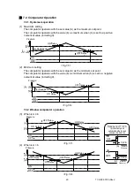
Page 20: ...s with the value b as minimum when b is set to a negative numerical value including 0 7 4 2 Window comparator operation 3 When is A b 4 When is A b OFF Delay ON Delay ON OFF b Dead band Pressure A A b OFF Delay ON Delay ON OFF b Dead band Pressure A A b 設定値 A b には1 F S の接断差が内部で自動的に 設定されます ON OFF b ON OFF A Greater Pressure Greater Pressure 1 F S Dead band of 1 F S is internally set automatically f...

Page 21: ...by a user turn the power off and on to re calculate the setting values Or go back to Function Setting Mode and go back to Measurement Mode again No need to reset the filter 7 5 3 Loop check Regardless of the applied pressure display analog output and the comparator can be tested manually using keys Use for simulations such as wiring check of analog output and comparator output In the Measurement M...

Page 22: ...r follow the message to take an action 7 5 7 Backup of settings The built in EEPROM holds the set value and some operating state against power failure エラー表示 内 容 処置方法 圧力レンジの110 F S を超える圧力が印加 された時 又は表示値が6000を超えた時 圧力レンジの 10 F S 未満の圧力が印加さ れた時 又は表示値が 1999を超えた時 ゼロ点調整時 圧力レンジの 10 F S 範囲 外の圧力が印加されている時 大気圧に戻して 再度ゼロ点調整を 行って下さい 定格圧力値以内に戻して下さい Table 7 2 Error message Description Solution Adjust the value withi...

Page 23: ... wiring carrying high current Ground the product so that the specified ground point is electrically grounded See 4 1 Figure 4 1 and 4 2 Figure 4 2 Keep the product away from electrically charged machines or objects Conductive noise Use the stable power supply that is difficult to generate noise Install power supply or output measurement equipment in an environment that is impervious to being affec...

Page 24: ...y is considered as an incompatible one due to faults of our design or manufacturing we repair the product or replace it with a compatible one for free However note that the conditions below are excluded You or third parties other than us disassemble or modify the delivered product replace parts or add functions The information described in the user manual or catalog is not observed The product is ...

Page 25: ...25 TY GC62 010A Rev 2 MEMO ...

Page 26: ...ormation described in this user manual Copying or reprinting without permission is prohibited For other questions contact our sales office nearest you or call the number below GC62 Digital Differential Pressure Gauge User Manual April 2019 Rev 2 Website http www naganokeiki co jp lng eng NAGANO KEIKI CO LTD Head office 1 30 4 Higashi magome Ota ku Tokyo 143 8544 Phone 81 3 3776 5328 Fax 81 3 3776 ...

Reviews: